Drilling and bolting head for a bolting machine

a technology of bolting head and bolting machine, which is applied in the direction of bulkhead/pile, soil preservation, artificial islands, etc., can solve the problems of not being able to use, the assembly thus formed by the bolting head and its supporting arm is bulky, etc., and achieves the effect of easy handling, easy use and productivity improvemen

Active Publication Date: 2006-04-25
SANDVIK TAMROCK SECOMA
View PDF11 Cites 32 Cited by
  • Summary
  • Abstract
  • Description
  • Claims
  • Application Information

AI Technical Summary

Benefits of technology

[0004]The present invention aims to avoid these disadvantages by providing a drilling and bolting head of highly compact structure, designed for use and transport in mine galleries of small height and under other conditions where the available space is limited, by virtue of a reduction in the overall size both in height and laterally and in headway, while at the same time preserving easy handling qualities and great ease of use as well as good stabilization in the working position.
[0013]Thus, the bolting head which is the subject of the invention possesses a part orientable about a vertical axis, along which is arranged a jack which performs the twofold task of “the advance to the block” for the slideway and of acting as a prop for supporting the roof of the gallery, this construction principle allowing especially compact implementation integrating all the necessary functions.
[0014]In an advantageous embodiment, in terms of compactness, the intermediate support is mounted and guided in translational movement on a transversely arranged table provided with means for connecting the latter to one end of the carrying vehicle, motorized means being provided for controlling the displacement of the slide along the table. This embodiment dispenses with the customary supporting arm.
[0018]In addition, the intermediate support may be mounted pivotally about a longitudinal axis with respect to the slide or with respect to the front part of the supporting arm, depending on the embodiment, in order to “lay down” the bolting head when the latter is not in use, thus reducing its height and facilitating the displacements of the bolting machine equipped with this bolting head.
[0023]The invention thus provides, overall, a bolting head which is especially compact for both bolting in the vertical direction and in the forward / rearward direction, particularly when the customary supporting arm is replaced by a table affording a transverse and also raising movement, while the vertical axis of advance to the block coincides with the pivot axis of the slideway. The telescopical functioning slideway, being adapted to the available height, is inscribed within the overall size of the machine, while remaining vertical, when said slideway is retracted, thus making it possible to displace the machine between two successive drilling and bolt setting positions, without the need for the slideway to be laid down. Thus, the design of the bolting head according to the invention eliminates a normally necessary rotational movement, thus allowing a time saving and therefore affording a gain in productivity.
[0024]Moreover, the means for prepositioning the slideway and the receptacle provided for the positioning and introduction of a bolt make the bolting head of the invention easy to handle and easy to use. With this in view, all the motorized translational and rotational movements of the bolting head are preferably radio-controlled movements.

Problems solved by technology

The assembly thus formed by the bolting head and by its supporting arm is bulky and does not allow use in mine galleries of small height; in this respect, not only must the overall size of the bolting head and of its supporting arm be taken into account, but also the considerable range resulting from this in terms of the movements for bringing the bolting head into each desired working position and the movements for this bolting head to pass from one position to another.

Method used


Image

  • Drilling and bolting head for a bolting machine
  • Drilling and bolting head for a bolting machine
  • Drilling and bolting head for a bolting machine

Examples


second embodiment

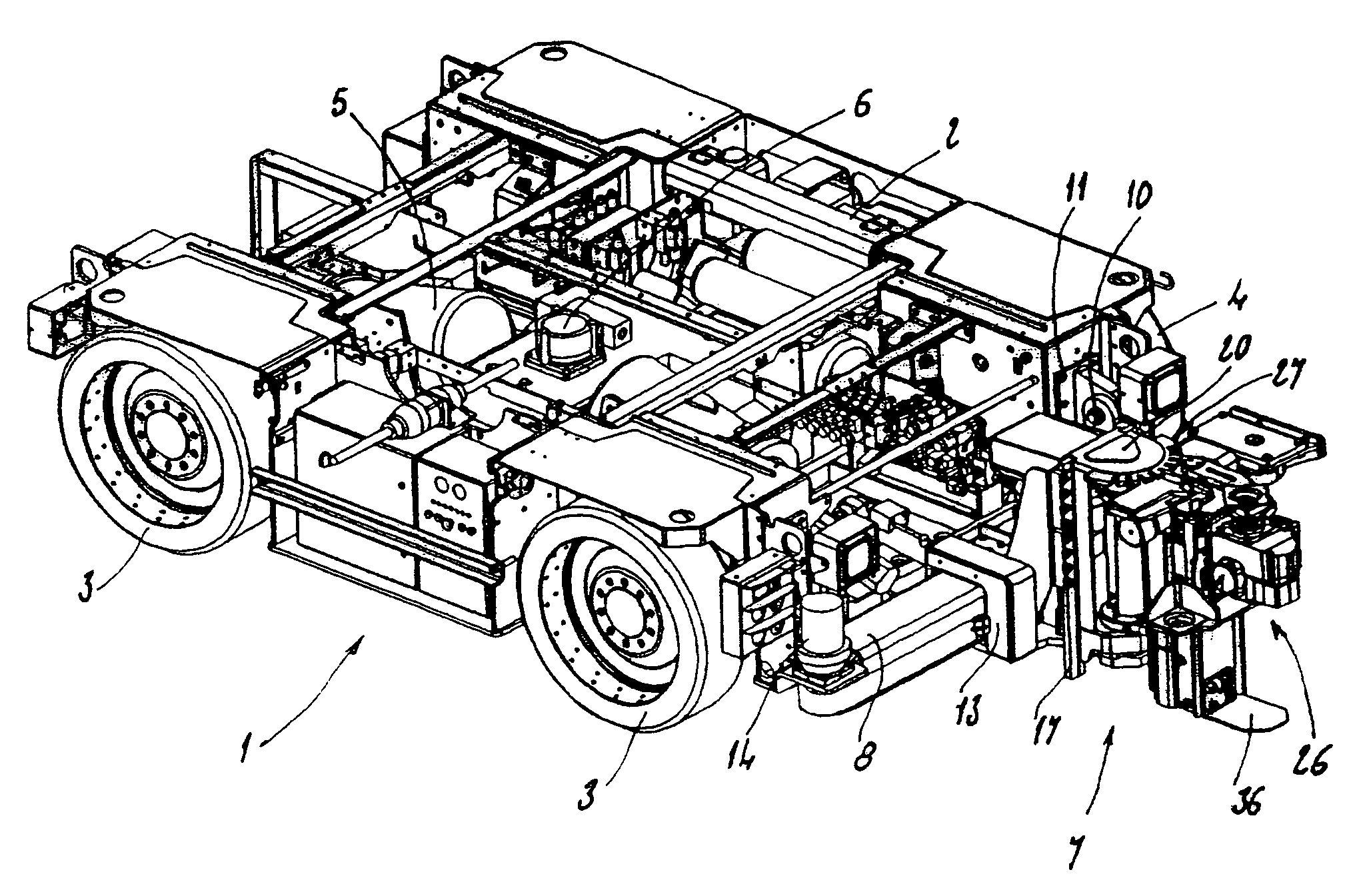
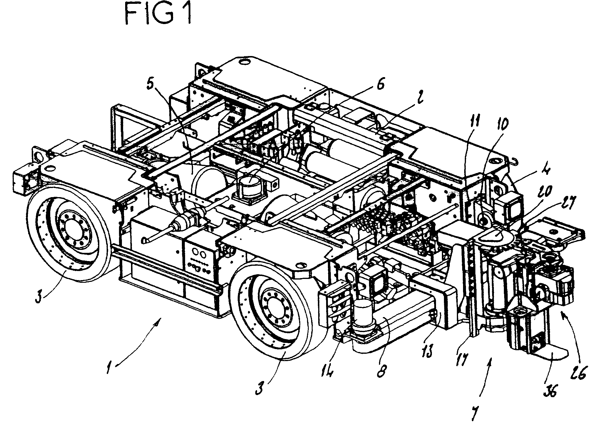
[0054]FIGS. 6 and 7 illustrate, partially, the bolting head 7 which is the subject of the present invention.

[0055]In this second embodiment, the table 8 and the slide 13 of the preceding embodiment are replaced by a telescopic supporting arm 43 of relatively short length. The supporting arm 43, which extends substantially horizontally, is composed of a rear element 44 and of a front element 45 mounted slideably within the rear element 44. This rear element 44 is mounted pivotally about a vertical axis 46 on a fork joint 47 fastened at the front of the chassis of the carrying vehicle (not illustrated here). At the front end of the front element 45 of the supporting arm 43 is mounted a vertical end plate 48 (equivalent to the slide 13 of the first embodiment) which is provided with vertical guide shoes 15 forming the vertical sliding guides of the moveable support 16 of the bolting head 7 (illustrated partially here).

[0056]A lateral jack 49 controls the pivoting of the supporting arm ...

first embodiment

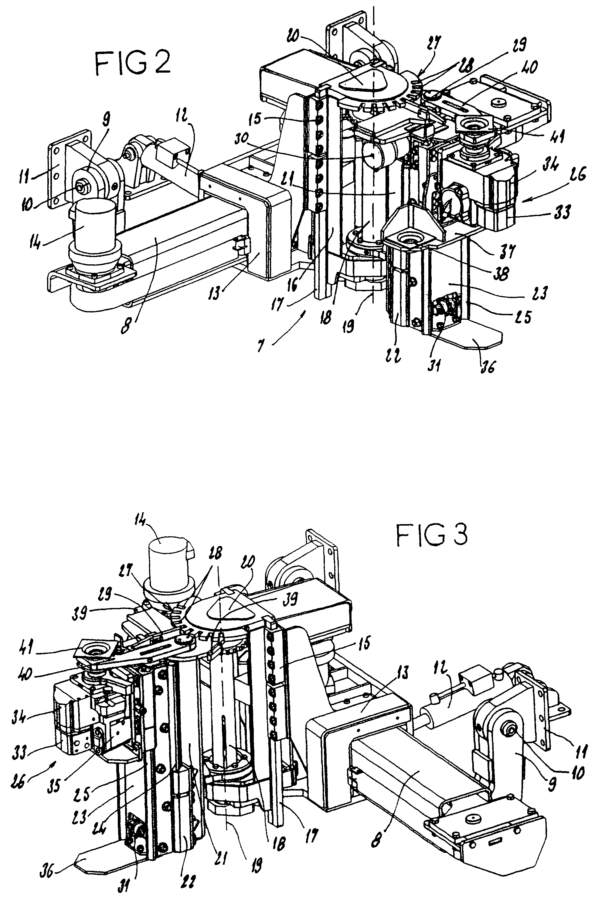
[0059]Referring more particularly to FIGS. 8 and 9, the upper steady rest 40 of the first embodiment is replaced here by a steady rest 53 of the same function, formed by an oblique arm 54 articulated on the beam 21 about a vertical axis 55 located on the side of the bolting head 7, at an intermediate height. The end of the arm 54 carries an opening gripper 56 capable of having the drilling tool passing through it in order to ensure the guidance of the latter. The pivoting mounting of the arm 54 allows the lateral retraction of the steady rest 53. Furthermore, means 57 can ensure the indexing of the arm 54 in one or more angular positions, in particular the position of use in which the gripper 55 is coaxial to the drill 26. The opening of the gripper 56 allows a lateral introduction and extraction of the drilling tool or a lateral retraction of the steady rest 53 without the removal of the drilling tool. This opening of the gripper 56 may be carried out hydraulically by means of a de...


PUM


Abstract

The drilling and bolting head (7) of compact structure, is designed for use in mine galleries of small height. It comprises: a transverse table (8) connected to the carrying vehicle, preferably with a device (9 to 12) for lifting this table (8); a slide (13) displaceable along the table (8); an intermediate support (16) displaceable vertically on the slide (13); a vertical beam (21) mounted pivotally on the intermediate support (16); a vertical slideway (23) guided vertically on the beam (21); a drill (26), with a device (33, 34) for the drilling and setting of bolts, which is guided vertically on the slideway (23); motorized device (14, 18, 30) for controlling the various movements. The intermediate support (16) possesses an upper part (20) which can be used as a prop, in combination with a jack (18) arranged along the vertical pivot axis (19) of the beam (21).

Description

BACKGROUND OF THE INVENTION[0001]The present invention relates, in general terms to what are known as bolting machines intended for carrying out underground jobs, in particular in mine workings. This invention relates more particularly to a drilling and bolting head, also designated here more simply as a “bolting head”, provided for equipping such a bolting machine, the bolting head having a highly compact structure and being designed for use in mine galleries of small height, this head being mounted on a carrying vehicle, itself of small height.[0002]A bolting head is an assembly supported by a carrying vehicle and making it possible to set supporting bolts in a mechanized way in the roof of a mine gallery.DESCRIPTION OF THE PRIOR ART[0003]In the conventional design, a bolting head is mounted at the end of a supporting arm of adjustable length. The assembly thus formed by the bolting head and by its supporting arm is bulky and does not allow use in mine galleries of small height; i...

Claims


Application Information

Patent Timeline
Patent Type & Authority Patents(United States)
IPC IPC(8): E21B7/02E21D20/00
CPCE21D20/003
Inventor BARTHOMEUF, JEAN-CLAUDECOMORGE, ALAIN
Owner SANDVIK TAMROCK SECOMA
Why Eureka
Try Eureka