Plug-in connector between a circuit board and a back plane

a technology of back plane and circuit board, applied in the direction of coupling device connection, optical element, instruments, etc., can solve problems such as attenuation or interference of signals

Inactive Publication Date: 2006-04-25
ERNI PRODION GMBH
View PDF8 Cites 46 Cited by
  • Summary
  • Abstract
  • Description
  • Claims
  • Application Information

AI Technical Summary

Benefits of technology

[0021]Preferably, the plug-in connector consists of two essentially symmetrical halves, the parting plane of which lies essentially in the plane in which the optical means of transmission, for example, glass fibers, are arranged. This allows simple production of the two halves of the plug-in connector in the form of injection-molded parts. With this design, glass fiber lines as well as the means for coupling the optical signals coming from the back plane or the circuit board are embedded into the plug-in connector.

Problems solved by technology

In addition, because of the opto-electrical conversion, transmission losses always occur, which result in undesirable attenuation or interference of the signal.

Method used


Image

  • Plug-in connector between a circuit board and a back plane
  • Plug-in connector between a circuit board and a back plane
  • Plug-in connector between a circuit board and a back plane

Examples


Embodiment Construction

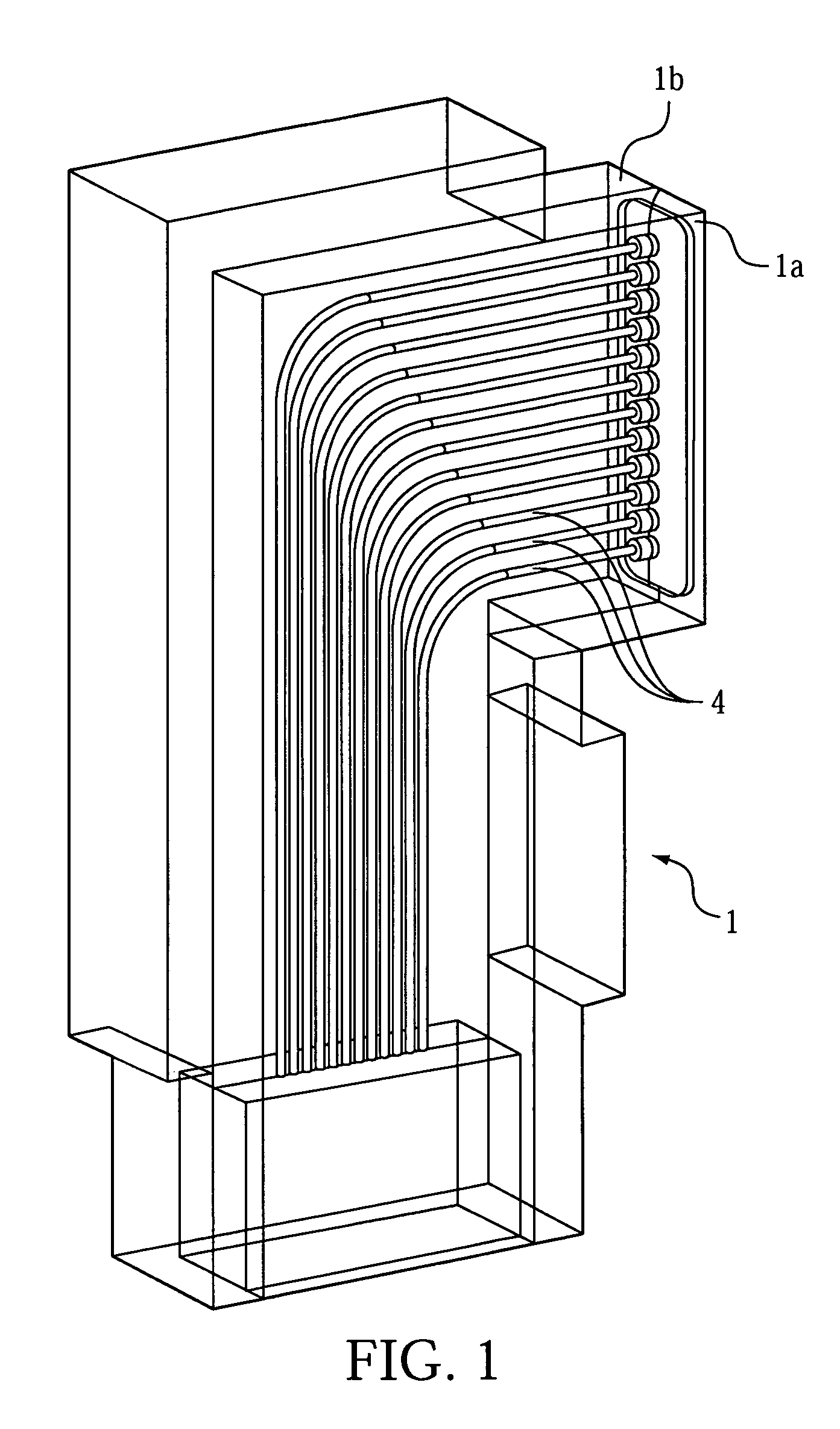
[0029]Referring in detail to the drawings, FIG. 1 shows a plug-in connector 1 that comprises two symmetrical halves 1a, 1b, preferably in the form of two plastic injection-molded parts. In the center plane of the plug-in connector 1, are arranged glass fiber lines 4 for transmitting optical signals. These glass fiber lines 4 can, however, also be replaced by plastic polymers.

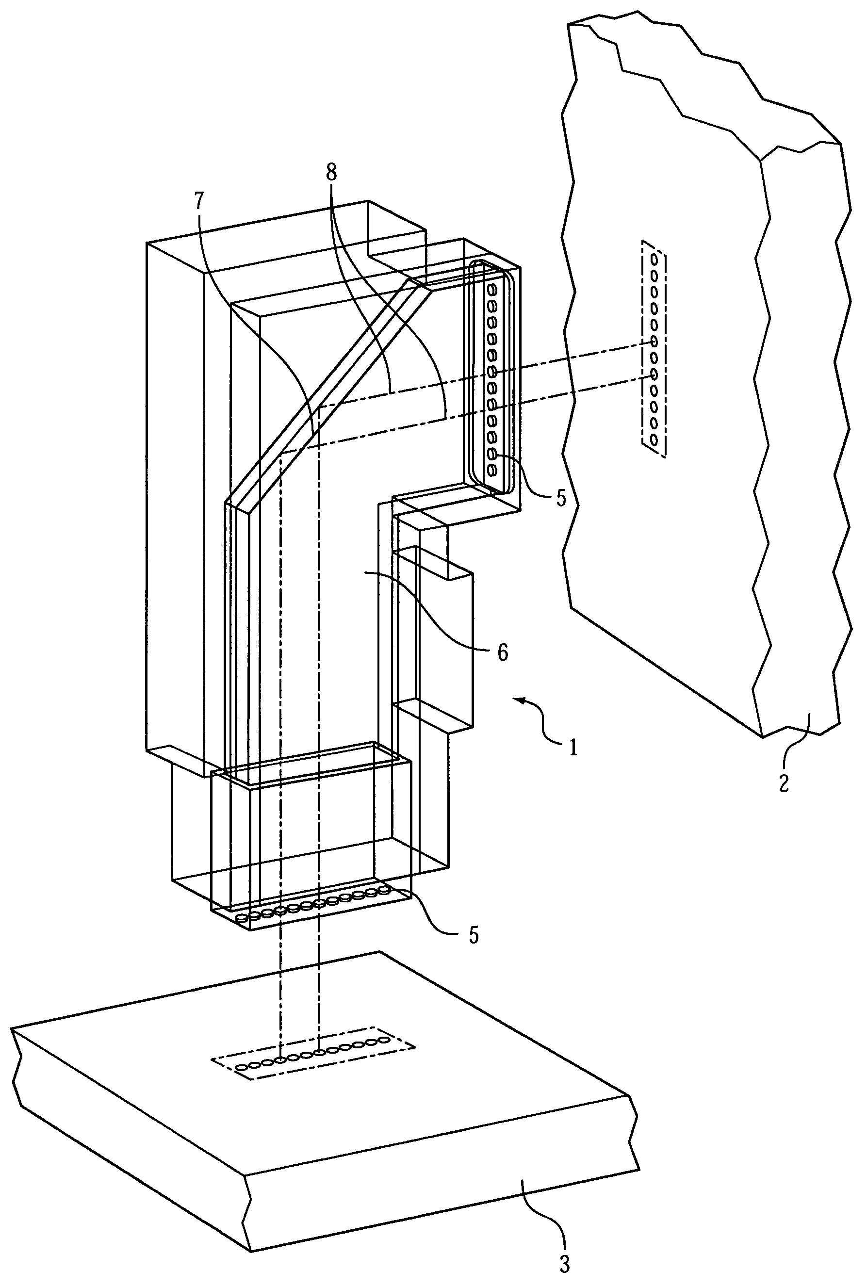
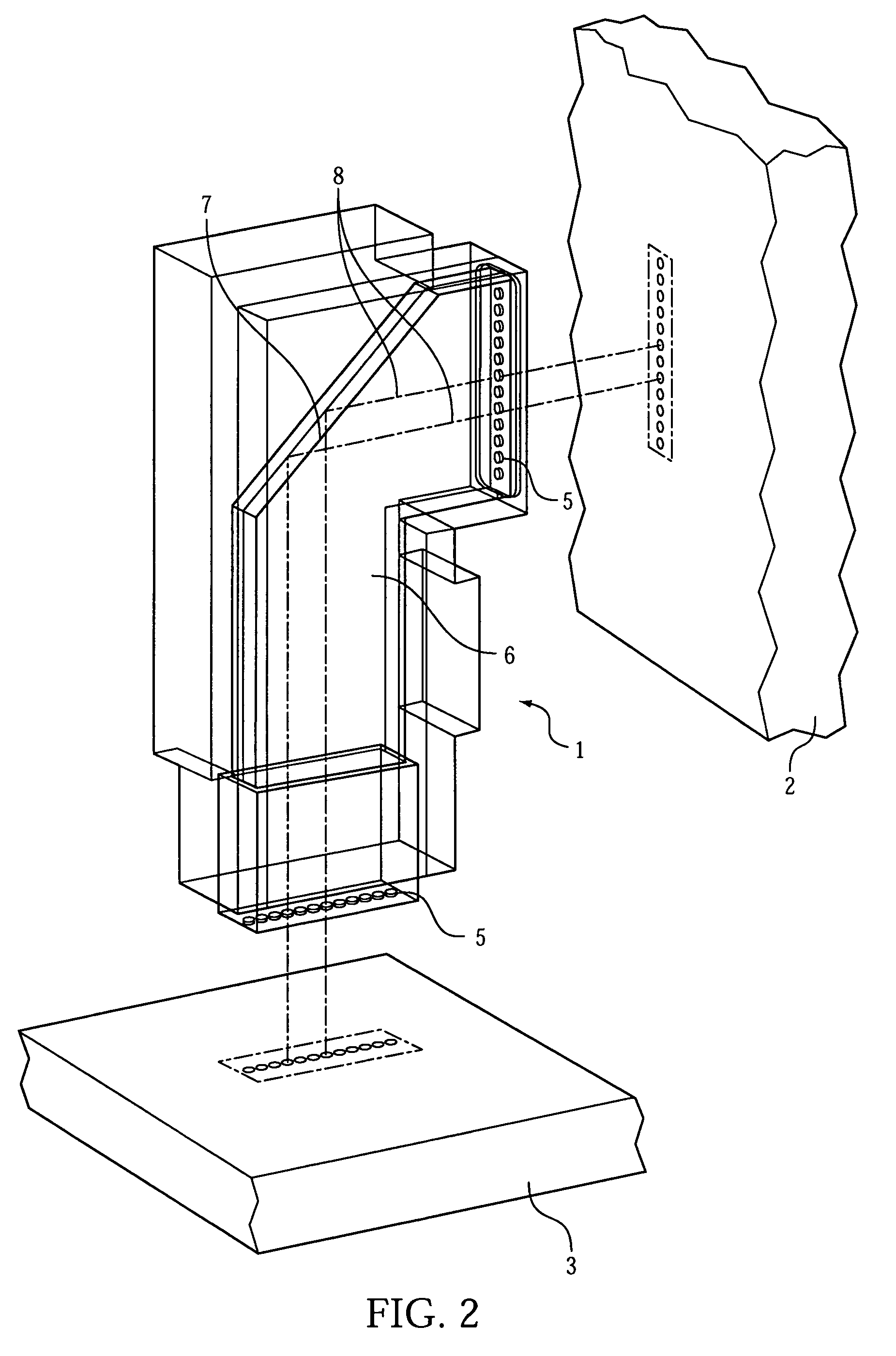
[0030]FIG. 2, shows another embodiment wherein the optical signal coming from the back plane 3 and / or the circuit board 2 is coupled into the plug-in connector 1 at the in-coupling points 5. In particular, this optical signal is coupled into a prismatic body 6 that has a reflective surface 7.

[0031]This reflective surface 7 can be produced, for example, via vapor deposition of a metallic layer that reflects the light. To illustrate the beam path in the plug-in connector 1, several optical paths 8 are drawn in the prismatic body 6 with dash-dotted lines. For this purpose, the incoming optical signal must be bundle...


PUM


Abstract

A plug-in connector for connecting and transmitting signals from a circuit board to a back plane wherein the plug-in connector comprises an optical conductor for transmitting optical signals into the plug-in connector and at least one mirror coupled to the optical conductor for deflecting light at an approximately 90° angle in the plug-in connector. There is also a lens system disposed adjacent to the mirror and coupled to the optical conductor for coupling the light into the plug-in connector. This optical conductor can comprise a plurality of glass fiber lines for coupling in the optical signal. Alternatively, this optical conductor could be lines formed from plastic polymers.

Description

CROSS REFERENCE TO RELATED APPLICATIONS[0001]This application claims priority under 35 U.S.C. 119 from German Application Serial No. 10239575.6 filed on Aug. 23, 2002.BACKGROUND OF THE INVENTION[0002]The present invention relates to a plug-in connector for plugging in optical light.[0003]Plug-in connectors for connecting a circuit board with a back plane are known to a person skilled in the art, in many different embodiments. These plug-in connectors connect the back plane with an interchangeable circuit board, whereby both a mechanical connection and a signal transmission take place via the plug-in connector, between the circuit board and the back plane. Thus, this connection usually requires standardized electrical contact connectors transmission lines for transmitting electrical signals from the back plane to the circuit board or back.[0004]Because of the increasing miniaturization of electronic components, as well as the constantly increasing demands with regard to transmission ...

Claims


Application Information

Patent Timeline
Patent Type & Authority Patents(United States)
IPC IPC(8): G02B6/38G02B6/42G02B6/43
CPCG02B6/3885G02B6/421G02B6/43G02B6/4214G02B6/4249
Inventor LAPPOHN, JURGEN
Owner ERNI PRODION GMBH
Why Eureka
Try Eureka