
Prosthetic mounting device

a technology for mounting devices and prostheses, which is applied in dental prostheses, dental surgery, medical science, etc., can solve the problems of insufficient bone tissue density and the installer cannot continue to use the rotary driver,

Inactive Publication Date: 2006-04-25
INTRA LOCK INT
View PDF14 Cites 22 Cited by
  • Summary
  • Abstract
  • Description
  • Claims
  • Application Information

AI Technical Summary

Problems solved by technology

This prevents an installer from continuing to use the rotary driver when bone density requires that a different instrument, such as a ratchet wrench, be used for the remainder of the installation.
If the handle never breaks off during installation, the installer knows that bone tissue density is insufficient to properly support a prosthesis.

Method used


Image

  • Prosthetic mounting device
  • Prosthetic mounting device
  • Prosthetic mounting device

Examples


first embodiment

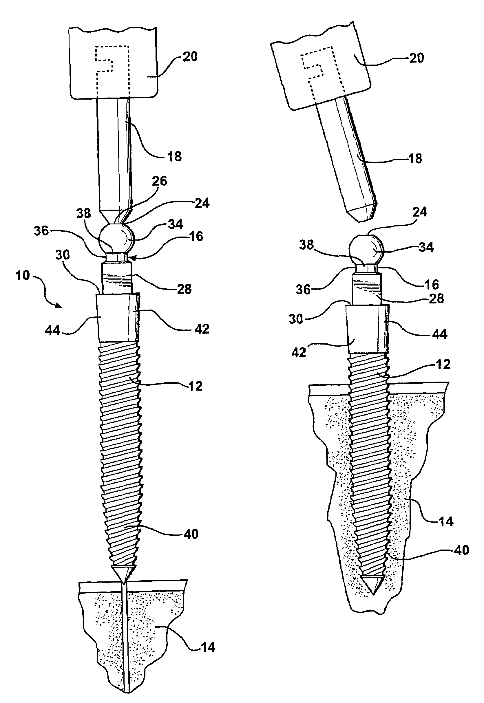
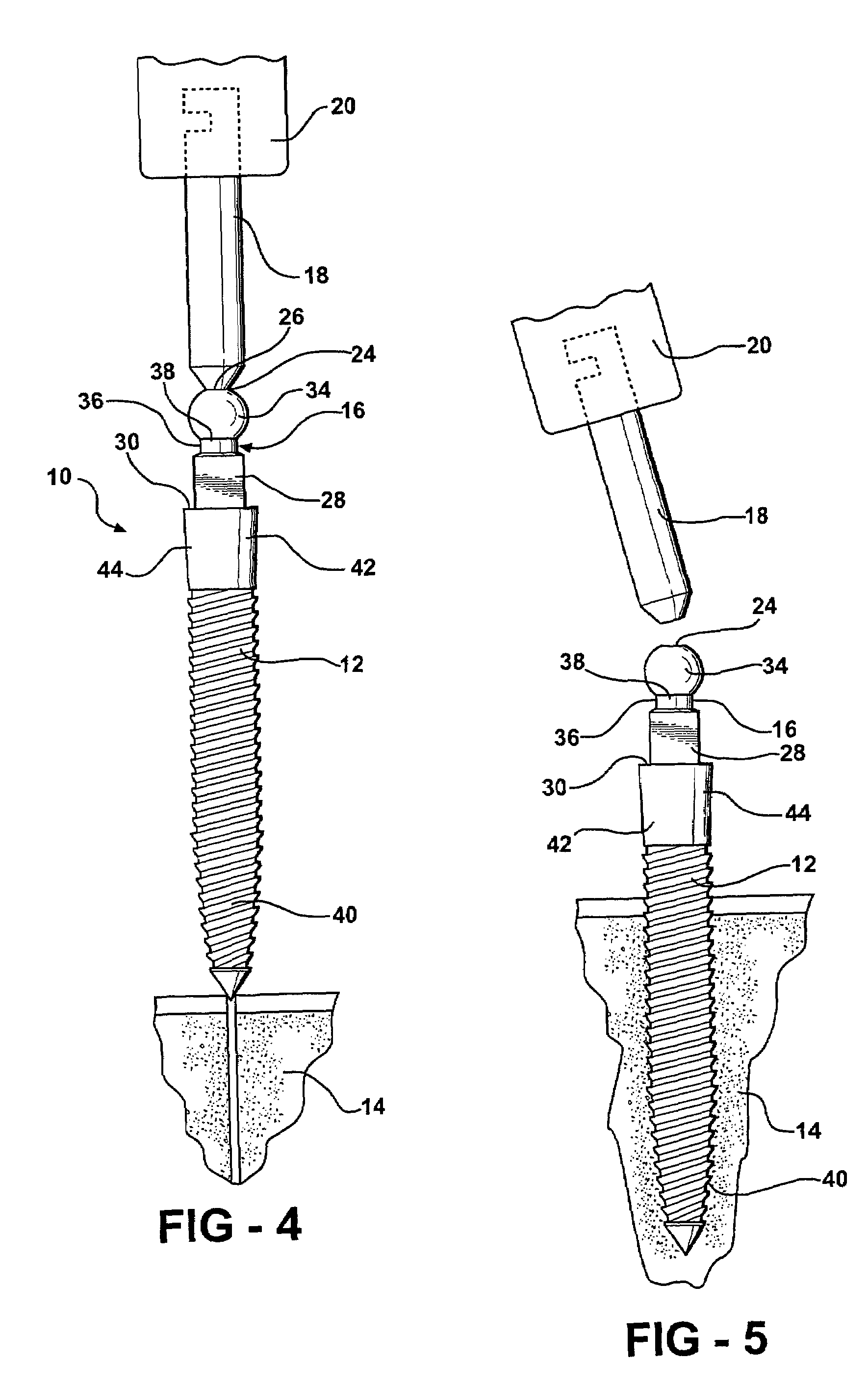
[0045]In practice, a device 10 constructed according to the invention can be secured in bone tissue 14 by first transporting the device 10 in a sterile condition within a sterile package. When the time comes to install the device 10, the package is opened and a rotary driver 20 is connected to the handle 18. The rotary driver 20 is then used to withdraw the device 10 from the package and to transport the device 10 to the surgical site. The mounting device 10 is then screwed into bone tissue 14 by first engaging the threaded shaft 12 with a pilot hole formed into the bone tissue 14 through the soft tissue 14 covering the jaw bone as shown in FIG. 4. The rotary driver 20 is then operated to rotate the device 10 until the handle 18 either breaks off or the device 10 is fully seated to a pre-determined depth.

[0046]If bone density is sufficient to properly support the device 10 and an attached prosthesis, the handle 18 breaks off before the device 10 reaches its full pre-determined depth...

embodiment 10

[0051]Because the second mounting device embodiment 10′ includes no integral installation handle, the invention also comprises a driver adapter 50 that receives the O-ball 34′ and the square nut 28′ into a complementary-shaped recess that's best shown at 52 in FIG. 13. An inner chamber 54 of the recess 52 is shaped to releasably retain the O-ball 34′ in snap-fit fashion. An outer section 56 of the recess 52 is shaped to rotatably engage the nut when the O-ball 34′ is fully received into the inner chamber 54.

[0052]An upper end 58 of the driver adapter 50 has a generally square cross-section shaped to be received into and rotatably engaged by a socket portion 60 a standard ratchet wrench 22′ as shown in FIG. 10. A peripheral trench 62 is formed around the upper end 58 of the driver adapter 50 and a rubber O-ring 64 is received into the trench 62 as shown in FIGS. 9, 10, 12, and 13. The O-ring 64 provides an interference fit between the upper end 58 of the driver adapter 50 and an inne...


PUM


Abstract

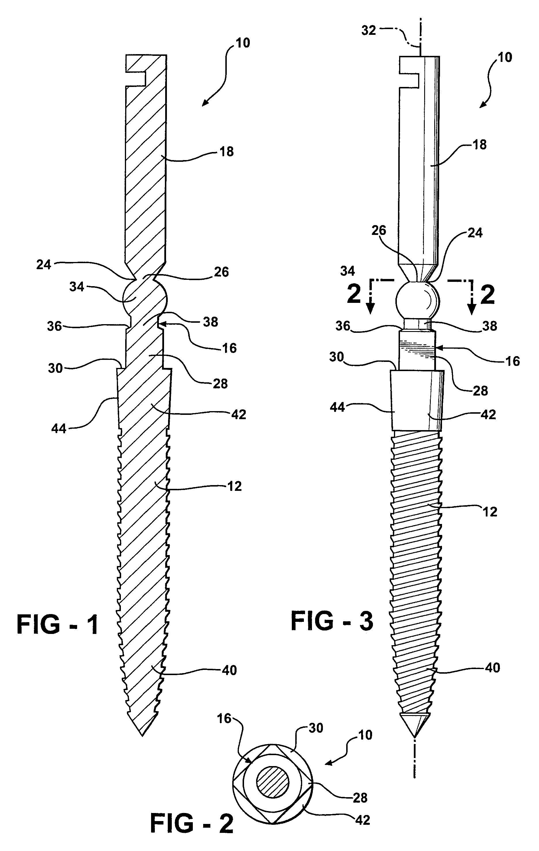
A prosthetic mounting device for securing a prosthetic device on bone tissue. The device includes a bone screw and a prosthetic abutment attached to an aft end of the screw. The abutment engages and rigidly supports a prosthesis. A tapered collar extends radially outward from around the aft end of the threaded shaft. In one embodiment, the device also includes an installation handle connected to and extending axially from the abutment. A rotary driver is used to engage and rotate the handle. The handle detaches from the abutment under a predetermined torque load both to cue an installer that increased bone density requires that a different instrument be used and that bone density is sufficient to support both initial and long-term stabilization.

Description

CROSS-REFERENCES TO RELATED APPLICATIONS[0001]Not ApplicableSTATEMENT REGARDING FEDERALLY SPONSORED RESEARCH OR DEVELOPMENT[0002]Not ApplicableBACKGROUND OF THE INVENTIONFIELD OF THE INVENTION[0003]This invention relates generally to a prosthetic mounting device for securing a prosthetic device on bone tissue.DESCRIPTION OF THE RELATED ART INCLUDING INFORMATION DISCLOSED UNDER 37 CFR 1.97 AND 1.98[0004]Conventional crowns, bridges and dentures have long been the standard prosthetic devices used to replace missing teeth. Such devices are secured to a jaw bone using a surgical anchor known as a dental implant or a prosthetic mounting device.[0005]The design of dental implants has developed considerably over the years since their initial conception by the ancient Egyptians. One of the more important developments is credited to the Swedish firm, Noblepharma. In the mid-1980s, Noblepharma developed and marketed a dental implant that resembled a natural tooth root. This implant, known as ...

Claims


Application Information

Patent Timeline
Patent Type & Authority Patents(United States)
IPC IPC(8): A61C8/00
CPCA61C8/0022A61C8/005A61C8/0057A61C8/0059A61C8/0066A61C8/0075A61C8/0087A61C8/0089A61C8/00A61C13/00
Inventor GIORNO, THIERRY
Owner INTRA LOCK INT
Learn More