Method and apparatus for combined magnetophoretic and dielectrophoretic manipulation of analyte mixtures

a combined magnetophoretic and dielectrophoretic technology, applied in the direction of fluid pressure measurement, liquid/fluent solid measurement, peptide measurement, etc., can solve the problem of limiting sample recovery, unable to distinguish between or isolate cell subpopulations that are characterized by, and inability to determine the extent to which magnetic labels have bound a target analyte, etc. problem, to achieve the effect of improving analyte recovery efficiency, reducing or eliminating the relaxation tim

Inactive Publication Date: 2006-04-25
BOARD OF RGT THE UNIV OF TEXAS SYST
View PDF53 Cites 66 Cited by
  • Summary
  • Abstract
  • Description
  • Claims
  • Application Information

AI Technical Summary

Benefits of technology

[0013]The following objects of the present invention are made possible as a result of this enhancement. First, the methods of the present invention allow several target analytes to be discriminated and isolated simultaneously in a single separation step. Second, target analytes do not have to be collected in the separator and, indeed according to the present invention, can be prevented from contacting any surface to which they may adhere during separation. This not only greatly reduces the problem of trapping of unwanted analytes within target analyte fractions, but also improves analyte recovery efficiencies. Third, apparatus according to the present invention can operate in any orientation, as well as in microgravity environments. Fourth, it is an object of the present invention to obtain discrimination that is much greater than that obtainable by previous methods. Fifth, because both the magnetophoretic (MAP) and dielectrophoretic (DEP) force fields used to position the analyte-label complexes are inhomogeneous in space, the positioning force may be greater than a sedimentation force, thus positioning according to the present invention can occur quicker than in cases where gravitational sedimentation is used. This reduces or eliminates the “relaxation time” prior to separation. Sixth, the present invention introduces improvements that allow bead labeling methodologies to be fully exploited.

Problems solved by technology

While the use of magnetic labeling methods is widespread, current methods have a number of significant disadvantages.
It is also impossible to determine the extent to which magnetic labels have bound a target analyte without additional measurement steps after magnetic collection.
For example, it is impossible to distinguish between or isolate cell subpopulations that are characterized by variations in the number of labels bound to their surfaces since all cells that bind labels, regardless of the number, are collected by current magnetic methods.
This typically limits sample recovery because of adhesion to the chamber or column and may entrap unwanted unlabelled analytes within the labeled analytes thereby limiting the purity of the recovered target analytes.
Nevertheless, the intrinsic dielectric properties of target particles, cells, or molecules, or of their dielectric labels may still not allow for sufficient discrimination between multiple target analytes in complex mixtures.
This precludes or limits the use of the methods for applications in microgravity environments such as space.
The need to attain a balance between dielectrophoretic and sedimentation forces also places constraints on the relative densities of the suspending medium that carries the analyte mixture and the analytes to be separated.

Method used


Image

  • Method and apparatus for combined magnetophoretic and dielectrophoretic manipulation of analyte mixtures
  • Method and apparatus for combined magnetophoretic and dielectrophoretic manipulation of analyte mixtures
  • Method and apparatus for combined magnetophoretic and dielectrophoretic manipulation of analyte mixtures

Examples


first embodiment

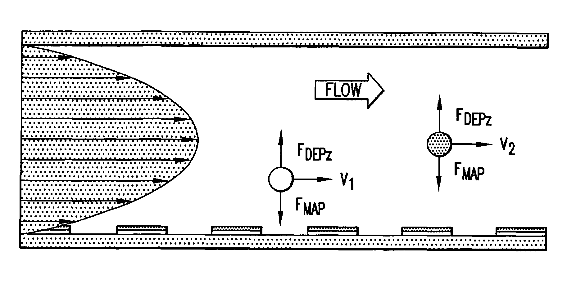
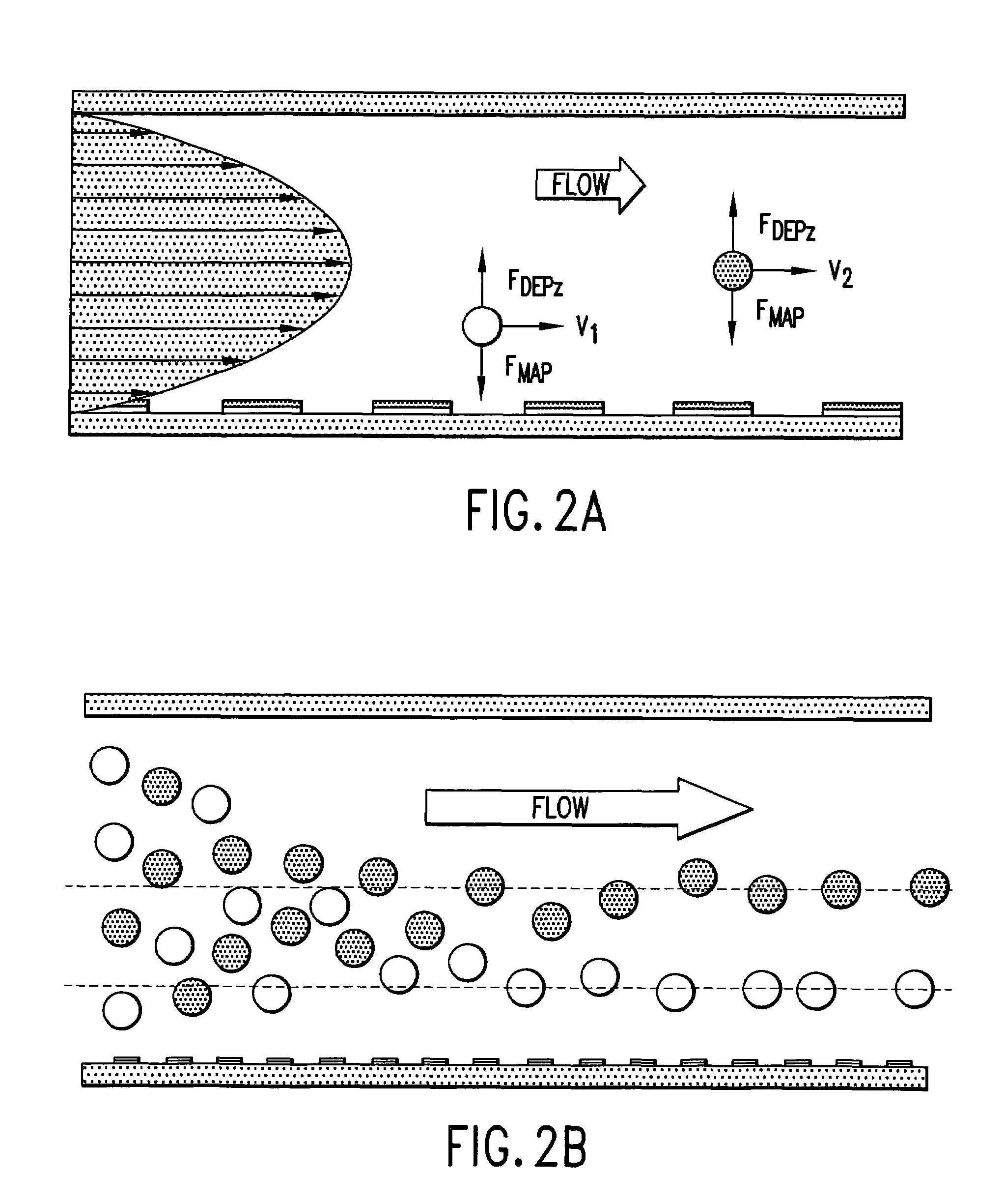
[0073]Two exemplary embodiments of separators are described that exploit analyte positioning by a combination of dielectrophoretic and magnetophoretic forces. In the first embodiment, which does not exploit the flow velocity profile of the carrier fluid and is suitable for continuous processing of samples, analyte mixtures may be flowed continuously through a chamber equipped with arrays of electrodes and magnetrodes. Analytes are then subjected to the combined dielectrophoretic and magnetophoretic forces resulting from the electric and magnetic fields. Providing they spend sufficient time within the flow channels, these forces move analytes sufficiently close to characteristic positions in the carrier medium flow profile stream at which the DEP and MAP forces balance so that they may be identified, separated, or isolated. Therefore, analytes emerge from the flow channel at positions that depend on their dielectric and magnetic characteristics. Different analytes may be characterize...

second embodiment

[0083]A second embodiment for continuous mode separation is shown in FIG. 9. FIG. 9 shows an alternate embodiment wherein all elements of the diagram with the exception of the outlet port VI are the same as described in FIG. 8. In FIG. 9, the outlet port arrangement comprises multiple ports configured so as to collect bands of fluid that travel through the flow chamber at certain defined distances from the electrode and magnetrode elements and from the walls of the flow chamber. Specifically, FIG. 9a shows how carrier fluid traveling through the flow channel at different distances from the flow channel walls can be removed from the flow channel through, for example, six exit ports. Analytes or labels or analyte-label complexes carried in the carrier medium at different distances from the chamber floor, at bottom of the diagram, are thereby caused to exit through different exit ports.

[0084]Description of batch-mode operation

[0085]In an exemplary separation using the batch mode, the f...


PUM

PropertyMeasurementUnit
dielectrophoretic forceaaaaaaaaaa
magnetic forceaaaaaaaaaa
dielectricaaaaaaaaaa

Abstract

Methods and apparatuses for discriminating matter utilizing dielectrophoresis combined with magnetophoresis. A sample having one or more constituents is injected into an inlet port of a chamber. A carrier medium flow is initiated at the inlet port to establish a flow within the chamber. A dielectrophoretic force is generated to act on the constituents of the sample. A magnetophoretic force is generated to act on the constituents of the sample. The dielectrophoretic force and magnetophoretic forces are balanced to position the constituents within the chamber. The constituents are then collected at one or more outlet ports of the chamber according to the dielectric and magnetic characteristics of the constituents. The constituents may be collected as a function of time-of-exit from the chamber and/or position within the chamber.

Description

[0001]This application claims priority to provisional patent application Ser. No. 60 / 211,757 filed Jun. 14, 2000, entitled, “Method and Apparatus for Combined Magnetophoretic and Dielectrophoretic Manipulation of Analyte Mixtures” by Peter R. C. Gascoyne, Jody V. Vykoukal, and Frederick F. Becker. The entire text of the above-referenced disclosure, including figures, is specifically incorporated by reference herein without disclaimer.[0002]The following issued U.S. patents are hereby incorporated by reference: U.S. Pat. Nos. 5,858,192, 5,888,370, 5,993,632, and 5,888,370. The following patent applications are hereby incorporated by reference: pending U.S. patent application Ser. No. 09 / 249,955 for “Method and apparatus for programmable fluidic processing” filed Feb. 12, 1999; pending U.S. patent application Ser. No. 09 / 395,890 for “Method and apparatus for fractionation using generalized dielectrophoresis and field flow fractionation” filed Sep. 14, 1999; provisional patent applicat...

Claims


Application Information

Patent Timeline
Patent Type & Authority Patents(United States)
IPC IPC(8): G01N27/26G01N27/72B01D57/02G01N33/483B03C1/00B03C1/01B03C1/24B03C5/00B03C5/02G01N27/447G01N30/00G01N33/561
CPCB03C1/00B03C1/01B03C1/24B03C5/026G01N27/44786G01N30/0005B03C5/028G01N2030/0065G01N2030/0015
Inventor GASCOYNE, PETER R. C.VYKOUKAL, JODY V.BECKER, FREDERICK F.
Owner BOARD OF RGT THE UNIV OF TEXAS SYST
Why Eureka
Try Eureka