Efficient venting means for a circuit breaker

a circuit breaker and efficient technology, applied in the field of circuit breakers, can solve the problems of reducing the electrical performance of the circuit breaker, and sudden increase in the surrounding area pressure, so as to reduce the volume of the cavity

Active Publication Date: 2006-04-25
SQUARE D CO
View PDF4 Cites 45 Cited by
  • Summary
  • Abstract
  • Description
  • Claims
  • Application Information

AI Technical Summary

Benefits of technology

[0008]A trip unit base is adapted to engage walls of the base and substantially enclose the chamber area to form a cavity. The trip unit base includes a complementary structure that opposes the structure such that the two are generally flush with one another. These two structures reduce the volume of the cavity that is presented to the passing gas.

Problems solved by technology

In addition, during the electrical interruption event, molten metal debris and carbon are produced, spraying outward in the direction of the gas, and can accumulate inside the circuit breaker.
The accumulation of this carbon and molten metal debris can eventually produce undesirable ground strikes or cross-phasing caused by dielectric breakdowns, reducing the electrical performance of the circuit breaker.
In addition, the sudden explosion of gas causes a sudden increase in pressure in the surrounding area of the explosion.
The forces caused by the pressure buildup inside the circuit breaker can cause undesirable internal or external physical damage to the housing and components of the circuit breaker.
In addition, the pollution caused by a buildup of molten metal debris and carbon inside the circuit breaker can eventually cause ground strikes or dielectric breakdowns between the phases of current in the circuit breaker.
Pressure blowouts that cause damage to a circuit breaker will fail present UL requirements and will fail customer expectations.
A damaged circuit breaker may also present a safety hazard as the blowout may expose internal components of the circuit breaker to the operator or may cause internal shorting or melting of circuit-breaker components not designed for high current loads.

Method used


Image

  • Efficient venting means for a circuit breaker
  • Efficient venting means for a circuit breaker
  • Efficient venting means for a circuit breaker

Examples


Embodiment Construction

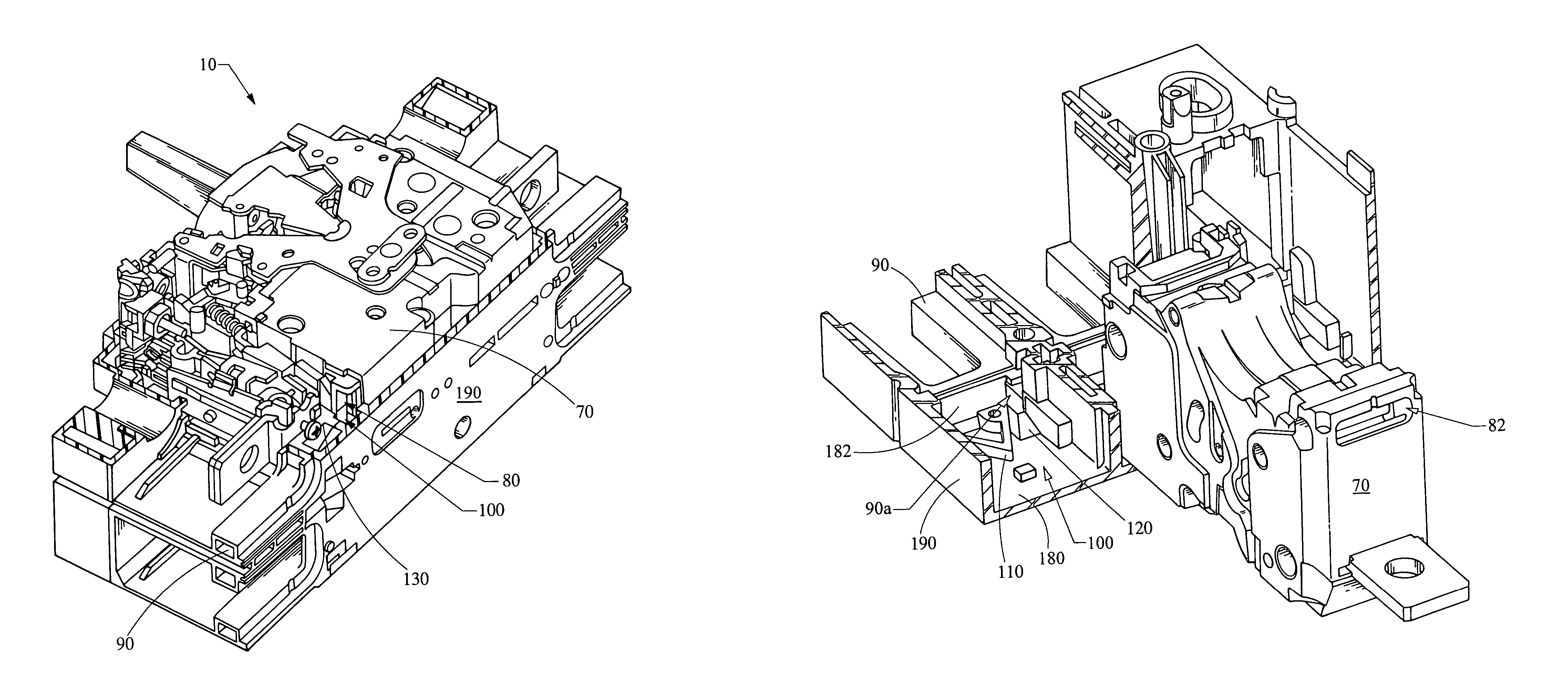
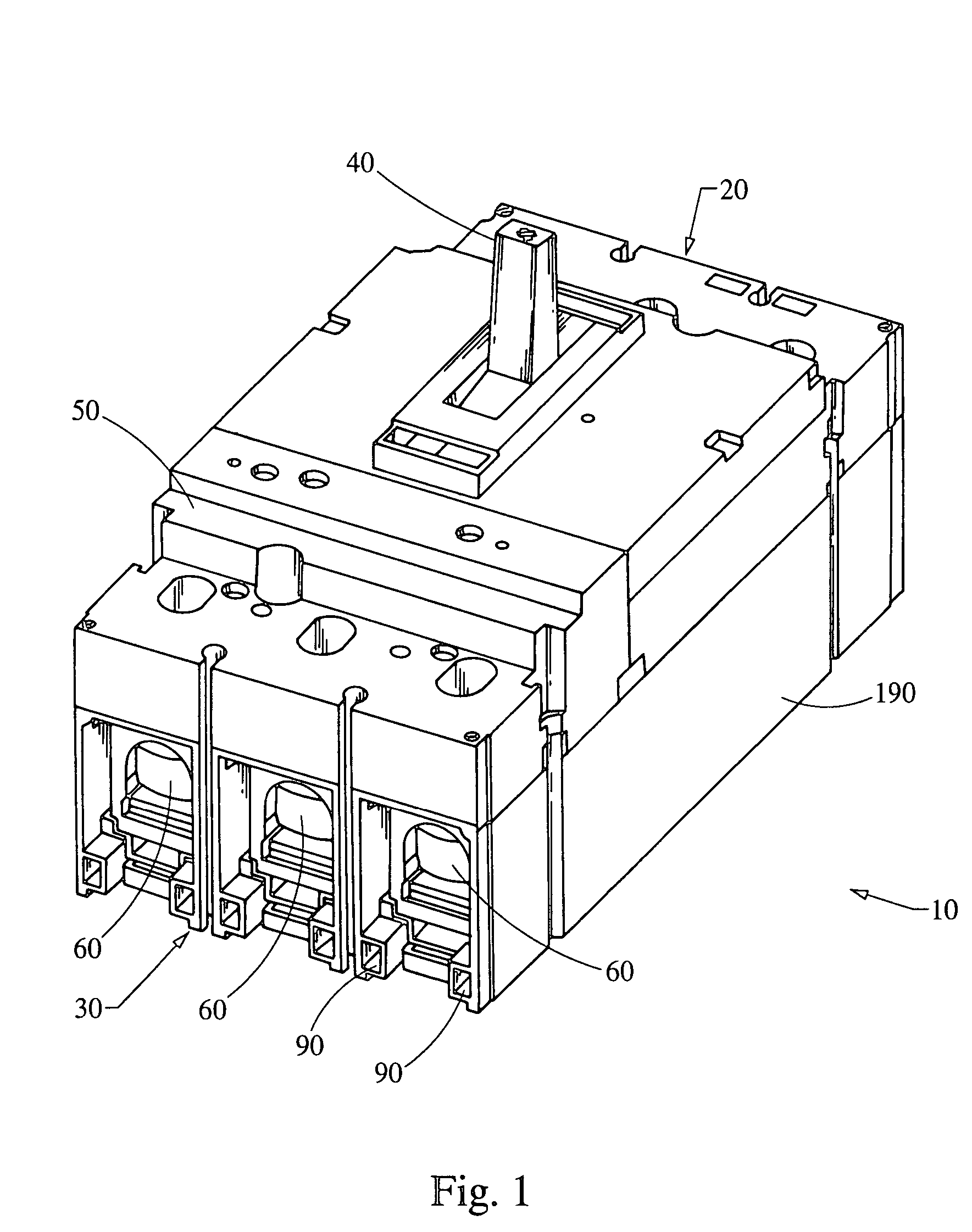
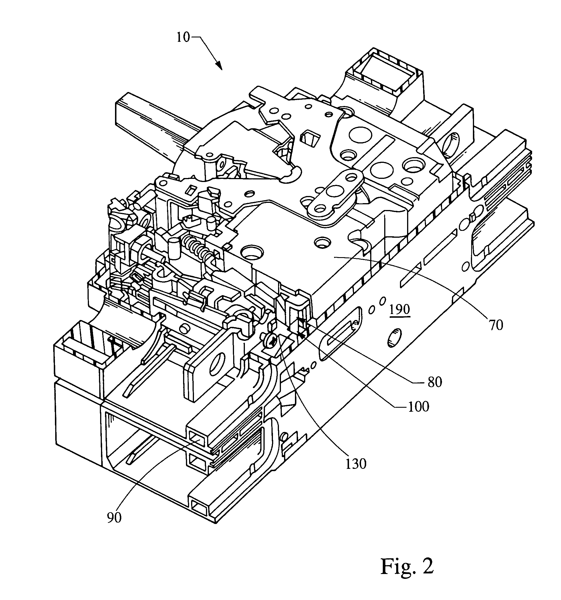
[0019]FIG. 1 illustrates a perspective view of a three-pole circuit breaker 10 having a line end 20 and a load end 30. A handle 40 is used to reset the circuit breaker or to turn the circuit breaker 10 on, off, or can indicate a TRIPPED condition of the circuit breaker 10. Proximate the load end 30 is a tripping unit 50, operable to trip the circuit breaker 10 in the event of an overload, short circuit, or thermal runaway condition. The tripping unit 50 is sized to fit into a base 190 of the circuit breaker 10. At the line end 20 and load end 30 of the circuit breaker 10, lug assemblies 60 are used to attach conductive cables (not shown) to supply electrical current to various loads in the electrical circuit to which the circuit breaker 10 is connected. During an electrical interruption event, caused by an overload, short circuit, or thermal runaway condition, for example, hot explosive gasses are built up internally and are released through a pair of vent chutes 90 in the correspon...


PUM


Abstract

An arrangement for reducing pressure inside a circuit breaker caused by gas produced during an electrical interruption event, including a base, an interrupter assembly, and a trip unit base. A structure having a surface is positioned in the base at an angle relative to a vent opening of the interrupter assembly. The trip unit base includes a complementary structure opposing the structure to form a cavity. The base includes a chamber area adjacent to an opening of a vent chute that leads away from the circuit breaker. During an electrical interruption event, hot explosive gas, carbon, and molten metal debris are directed away from the vent opening of the interrupter assembly along the angled surface of the structure and toward the opening of the vent chute. In this manner, pressure in the circuit breaker is reduced during an electrical interruption event, and undesirable buildup of debris is reduced.

Description

FIELD OF THE INVENTION[0001]This invention relates generally to circuit breakers, and, more specifically, to an efficient venting means for use in a circuit breaker.BACKGROUND OF THE INVENTION[0002]Circuit breakers are well known in the art, and are designed to trip in response to an electrical interruption event caused by an overload, short circuit, or thermal runaway condition, thereby opening the circuit to which the circuit breaker is connected and reducing the possibility of damage to the conductor wires or the loads connected to the circuit breaker. During the electrical interruption event, hot explosive gasses are generated and are released away from an interrupter assembly of the circuit breaker as the internal contacts inside the circuit breaker separate. In addition, during the electrical interruption event, molten metal debris and carbon are produced, spraying outward in the direction of the gas, and can accumulate inside the circuit breaker. The accumulation of this carb...

Claims


Application Information

Patent Timeline
Patent Type & Authority Patents(United States)
IPC IPC(8): H01H33/02H01H9/34H01H9/44H01H33/18H01H71/02H01H73/06
CPCH01H9/342H01H1/2058
Inventor FLEEGE, DENNIS WILLIAMLUKAS, ALLEN LESLIEVOLESKY, GARY ALLAN
Owner SQUARE D CO
Why Eureka
Try Eureka