Sample carrier for carrying a sample to be irradiated with an electron beam

a sample carrier and electron beam technology, applied in liquid/fluent solid measurement, instruments, machines/engines, etc., can solve the problems of sample carrier damage, sample carrier deformation during manipulation, and sample attached to the sample carrier, so as to increase the strength and stiffness of the sample carrier, increase the strength and stiffness, and increase the strength effect of the edge portion

Active Publication Date: 2006-04-25
FEI CO
View PDF5 Cites 44 Cited by
  • Summary
  • Abstract
  • Description
  • Claims
  • Application Information

AI Technical Summary

Benefits of technology

[0009]By making the edge portion of the sample carrier thicker than the middle portion, the strengthening effect of the edge portion increases, and the strength and stiffness of the sample carrier increase. The increase in strength and stiffness is achieved without limiting the ability to use the sample carrier in analyses in which tilting of the sample carrier is of importance, seeing as the thickness of the middle portion—which is of importance for analysis purposes—is not changed. As a result of the increase in strength and stiffness of the sample carrier, the risk of deformation of the sample carrier during manipulation, and damage to the sample attached thereto, is decreased.
[0010]An at

Problems solved by technology

As a result of the increase in strength and stiffness of the sample carrier, the risk of deformation

Method used


Image

  • Sample carrier for carrying a sample to be irradiated with an electron beam
  • Sample carrier for carrying a sample to be irradiated with an electron beam

Examples


Embodiment Construction

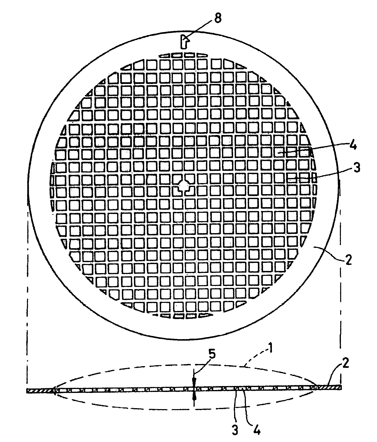
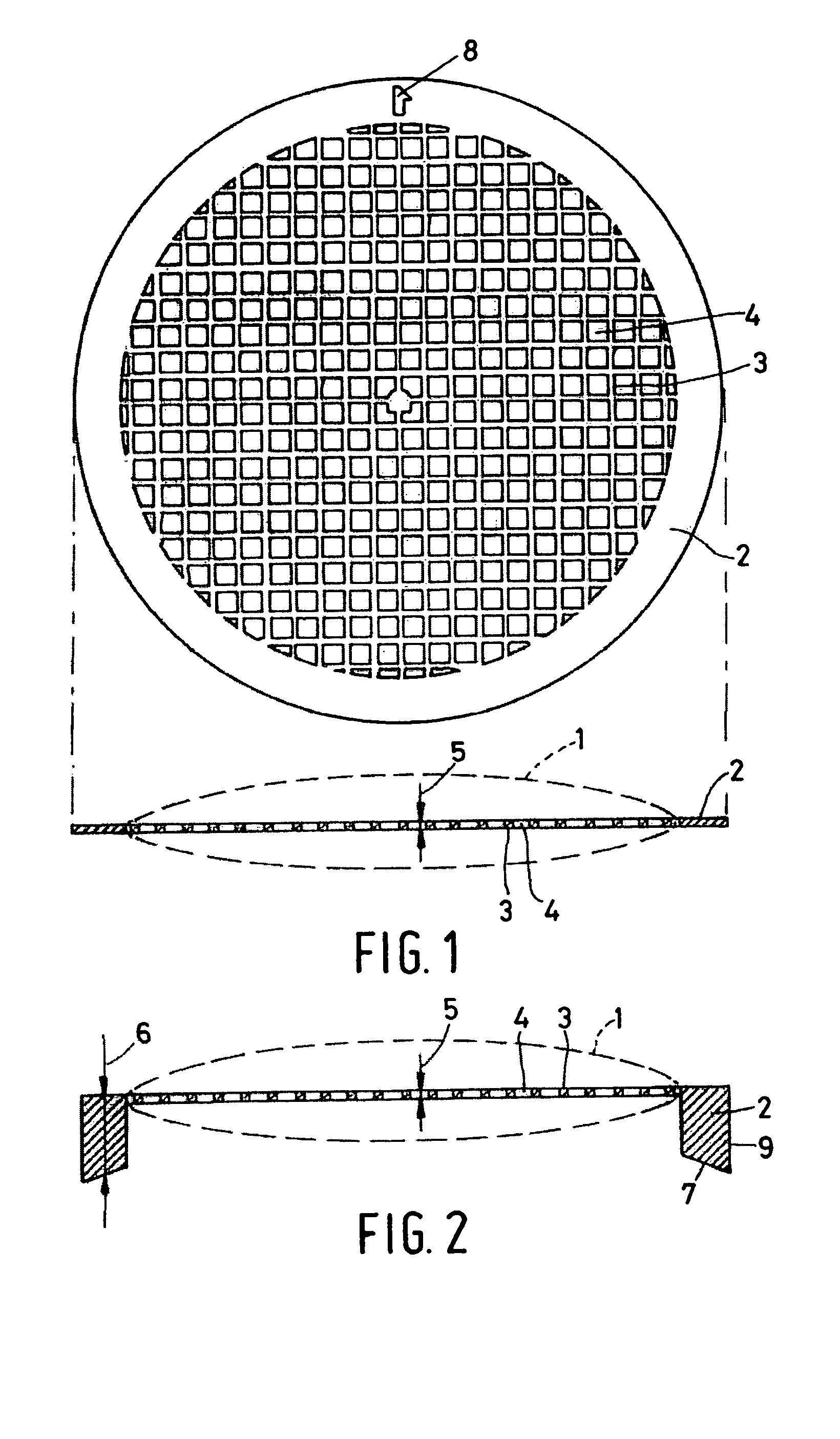
[0016]FIG. 1 shows a sample carrier as is commonly known from the state of the art. The sample carrier is made of copper, and has a diameter of 3.05 mm. The middle portion 1 consists of openings 4 of size 90×90 μm2 and bars 3 with a width of 35 μm. The electrons in an impinging electron beam will be able to pass through the openings 4, but will be blocked by the bars 3. As a result of this geometry, the transparency of the middle portion 1, in the case of a perpendicularly incident electron beam, is approximately 50%.

[0017]The middle portion 1 is surrounded by an edge portion 2 with a strengthening effect. The width of the edge portion is 0.225 mm. The edge portion 2 has no openings, with the exception of the orientation mark 8. The thickness 5 of the copper foil is uniform across the entire sample carrier, with a value of approximately 20 μm. A sample can be attached to the middle portion 1 in a manner known per se, whereby the regions of the sample that are of interest during an a...


PUM


Abstract

Sample carriers for use in Transmission Electron Microscopes (TEMs) and freely commercially available have the form of a gauze with a strengthening edge. The thickness of these known sample carriers is of the order of magnitude of 20 μm, and is uniform across the entire sample holder. The tiny thickness of these fragile sample carriers makes manipulation difficult. There is a desire to realize automatic introduction and removal of sample carriers in a TEM, seeing as this would make it possible to use the TEM continuously, without human intervention.
The invention describes a robust sample carrier whereby—both in the case of manual and automatic manipulation—deformation of and/or damage to the sample carrier is avoided. This is achieved by employing a strengthening edge portion 2 with a thickness 6 larger than the thickness 5 of the middle portion 1 of the sample carrier. The ability to use the sample carrier in analyses in which tilting is important is hereby not impeded.

Description

TECHNICAL FIELD OF THE INVENTION[0001]The invention relates to a sample carrier for carrying a sample to be irradiated with an electron beam, which sample carrier comprises a middle portion that is at least partially transparent to electrons, and an edge portion—located at the periphery of the middle portion—with a strengthening effect.BACKGROUND OF THE INVENTION[0002]Such a sample carrier is known from the catalog of the firm Structure Probe, Inc., with an address at 569 East Gay Street, West Chester, PA 19380, USA, under catalog number 2020C-XA, as described on the priority date of the present patent application on the website http: / / www.2spi.com / catalog / grids / square_mesh—200.shtml. The described embodiment concerns a round copper foil, whereby the circular middle portion is perforated with square openings. The square openings have dimensions of 90×90 μm2 and are separated from one another by bars with a width of 35 μm. The middle portion is surrounded in its entirety by an edge p...

Claims


Application Information

Patent Timeline
IPC IPC(8): G01N1/28G01N1/00H01J37/20
CPCH01J37/20
Inventor WAGNER, RAYMONDVAN DE WATER, GERBERT JEROEN
Owner FEI CO
Why Eureka
Try Eureka