
Adjusting gate pulse time intervals for reflected wave mitigation

a technology of reflected wave and gate pulse time interval, which is applied in the direction of power conversion system, electric motor speed/torque regulation, dynamo-electric converter control, etc., can solve the problems of increasing the number of components, increasing manufacturing costs, and system overvoltage, so as to reduce or mitigate the effects of reflected waves

Active Publication Date: 2006-04-25
ROCKWELL AUTOMATION TECH
View PDF10 Cites 74 Cited by
  • Summary
  • Abstract
  • Description
  • Claims
  • Application Information

AI Technical Summary

Benefits of technology

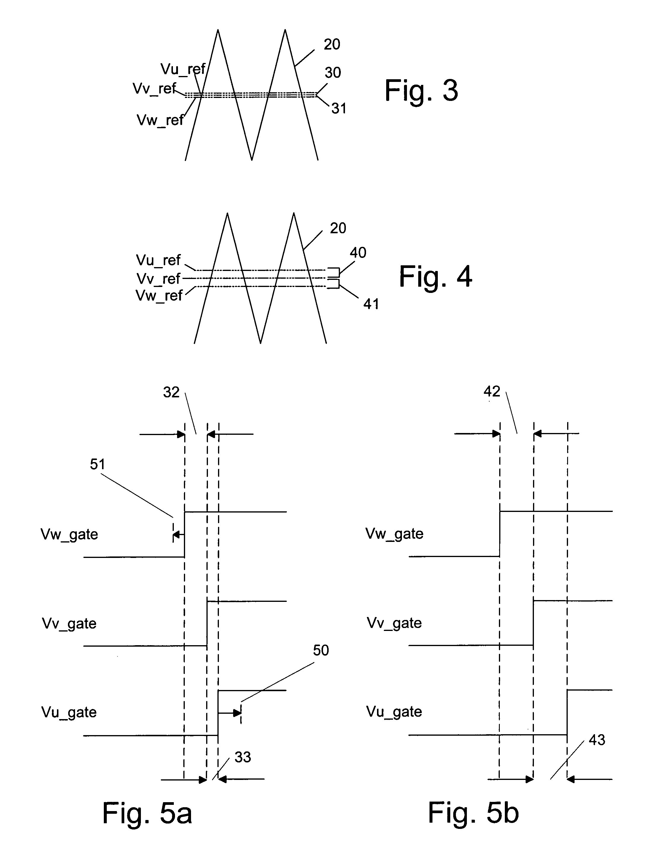
[0012]This enforced minimum time interval allows motor voltage ringing associated with a first power transistor (IGBT) gate pulse to decay before the next phase is allowed to switch. This, in turn, prevents an IGBT from turning on at peak motor terminal voltage. Motor voltages resulting from IGBT gate pulses become additive often exceeding two times source voltage, however by enforcing a minimum interval, greater than two times source voltage can be effectively controlled to a value approximately equal to twice source voltage.
[0013]The invention also reduces or mitigates the effects of inverter-induced polarity reversals, which is an inverter-driven event occurring most often when at least two phase signals intersect at a specific point in time. If not compensated, this results in 200% of bus voltage being applied when switching to the opposite side of the DC bus.

Problems solved by technology

Under certain operating conditions, these systems experience overvoltages due to transient waves that are reflected waves along the power lines between the motor and the control system.
This increases the number of components, however, as well as increasing manufacturing costs.
An uncontrolled region of operation occurs where the current changes polarity, where currents exist due to parasitic capacitances and where traveling wave conditions exist.

Method used


Image

  • Adjusting gate pulse time intervals for reflected wave mitigation
  • Adjusting gate pulse time intervals for reflected wave mitigation
  • Adjusting gate pulse time intervals for reflected wave mitigation

Examples


Embodiment Construction

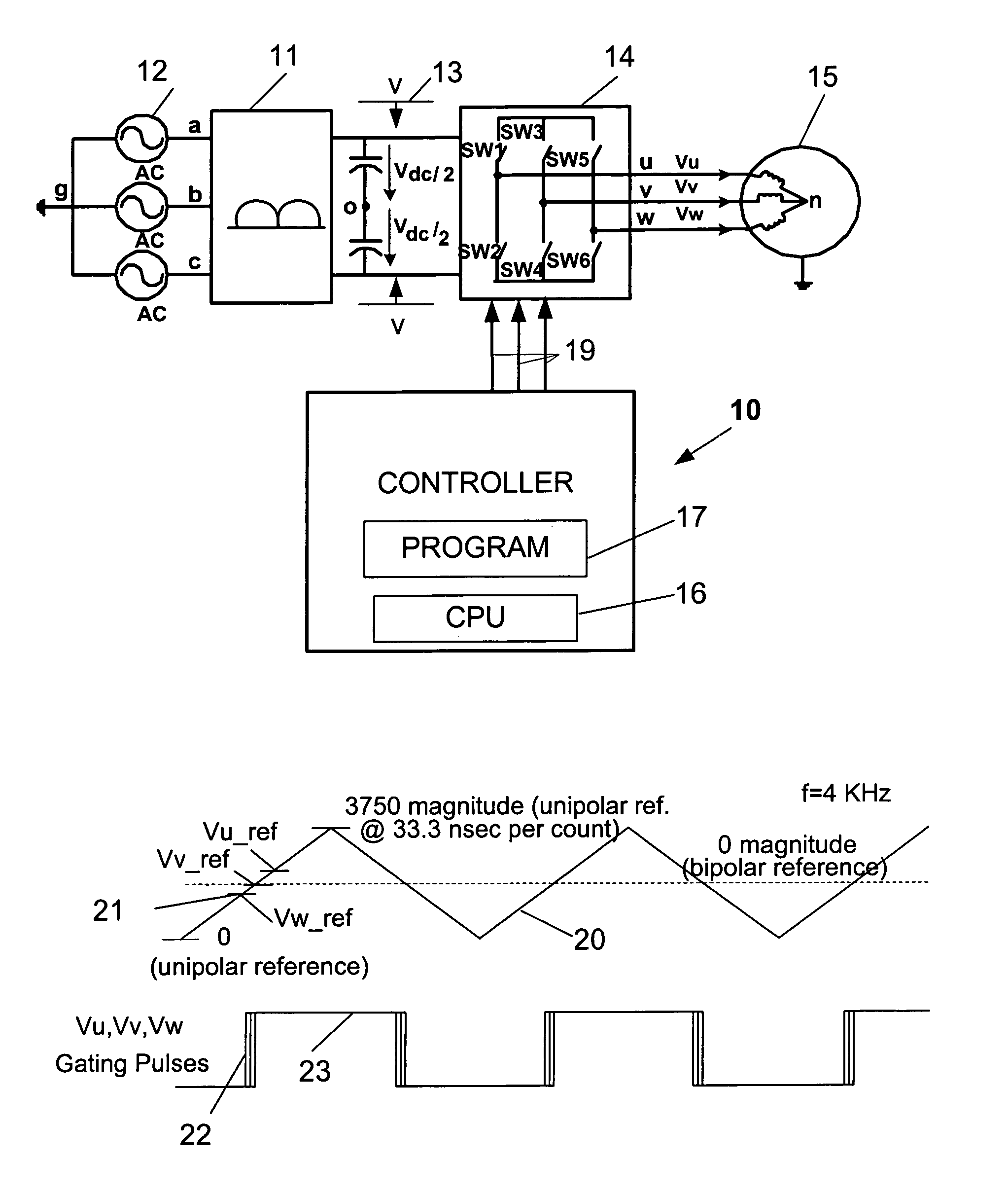
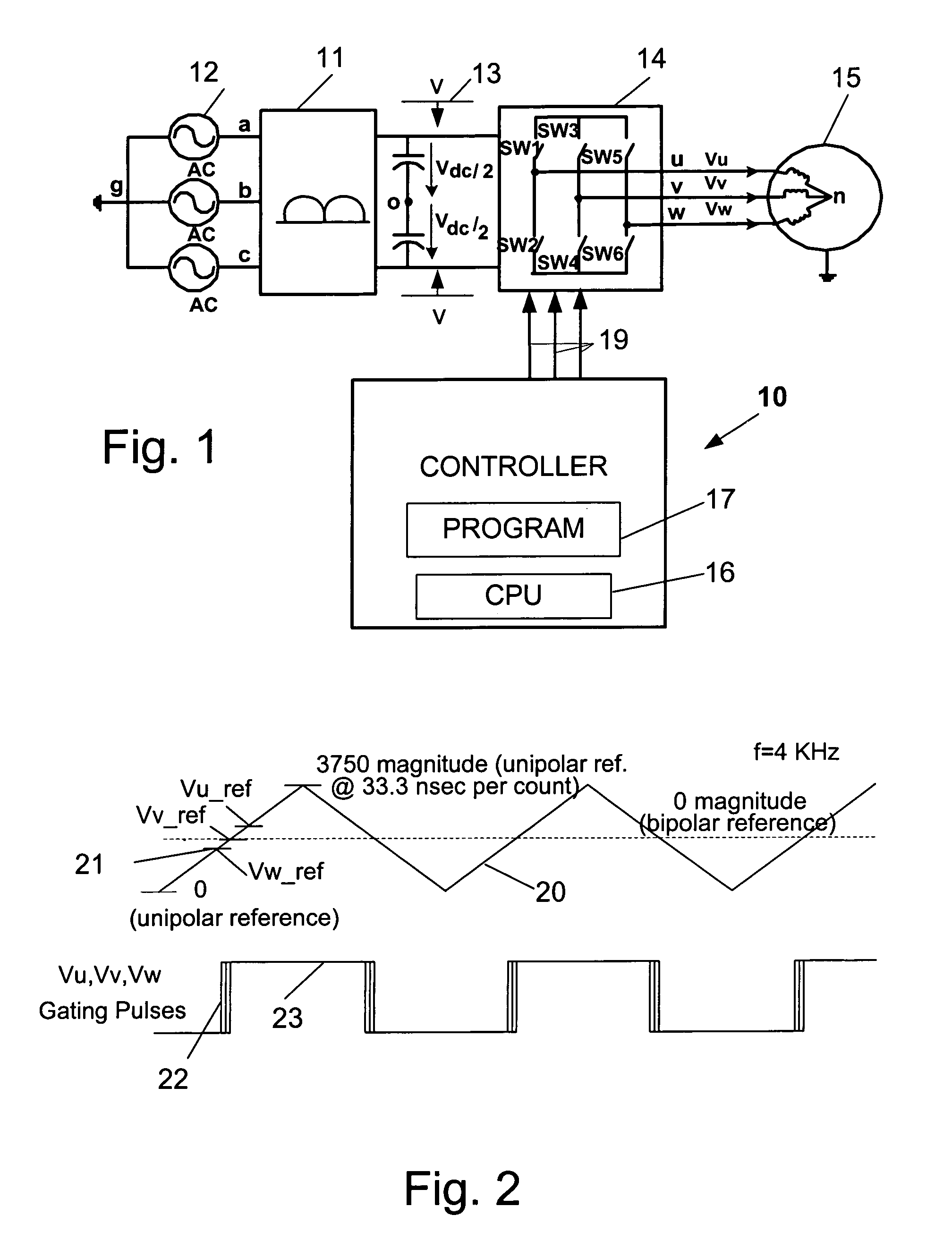
[0030]FIG. 1 illustrates a block diagram of an AC drive controller 10 for controlling an AC-to-DC converter 11 for converting three-phase AC source voltages from an AC voltage supply 12 to DC voltages, Vdc, on a DC bus 13. The DC bus 13 interfaces the AC-to-DC converter 11 to a DC-to-AC inverter 14, which is typically a three-phase bridge network of solid state switches SW1—SW6, preferably IGBT's, which are switched at high frequency to generate pulse width modulation (PWM) or other types of modulated low frequency power signals Vu, Vv, Vw, which are supplied to an AC motor 15.

[0031]The controller 10 includes a microelectronic CPU 16 operating according to instructions in a control program 17 stored in memory. The program 17 includes instructions for performing regulation of a DC bus voltage and regulation of current supplied to the motor 15. The controller provides gating signals through outputs 19 to control the switching of the switches SW1—SW6 in the inverter 14.

[0032]FIG. 2 sho...


PUM


Abstract

Methods and apparatus for controlling switching in a DC-to-AC inverter to prevent overvoltages applied to an AC motor by determining the switching order of the phase voltage signals, providing gating signals at switching intervals by modulating a carrier wave with the phase voltage signals, comparing the switching intervals to a predetermined minimum time interval sufficient for reflected wave transients to dissipate, and adjusting the switching intervals to be at least equal to the predetermined minimum time interval.

Description

CROSS-REFERENCE TO RELATED APPLICATIONS[0001]NOT APPLICABLESTATEMENT REGARDING FEDERALLY SPONSORED RESEARCH[0002]NOT APPLICABLETECHNICAL FIELD[0003]The field of the invention is control systems for controlling the operation of AC motors.BACKGROUND ART[0004]A well known type of AC drive includes an AC-to-DC converter for converting three-phase AC source voltages to DC voltages on a DC bus. The DC bus interfaces the AC-to-DC converter to a DC-to-AC inverter, which is typically a three-phase bridge network of solid state switches, which are switched at high frequency to generate pulse width modulation (PWM) or other types of modulated low frequency power signals which are supplied to an AC motor. Under certain operating conditions, these systems experience overvoltages due to transient waves that are reflected waves along the power lines between the motor and the control system.[0005]One way of mitigating these reflected waves is to place chokes and passive filter components in the lin...

Claims


Application Information

Patent Timeline
IPC IPC(8): H02P3/18H02P3/00
CPCH02M1/14H02P27/08H02P4/00
Inventor THUNES, JERRY D.KERKMAN, RUSSEL J.MATSUO, TAKAYOSHI
Owner ROCKWELL AUTOMATION TECH
Learn More