Driven equilibrium and fast-spin echo scanning

a technology of driving equilibrium and fast spin, applied in the direction of magnetic measurement, instruments, measurement devices, etc., can solve the problems of increasing the number of scans of patients that must be performed and the time necessary to complete such scans, increasing the time necessary for medical nmr imaging and patient throughput, etc., to achieve the effect of reducing the time period between scans and faster acquisition of image data

Inactive Publication Date: 2006-04-25
FONAR
View PDF6 Cites 10 Cited by
  • Summary
  • Abstract
  • Description
  • Claims
  • Application Information

AI Technical Summary

Benefits of technology

[0026]Thus, the multi-echo NMR imaging sequence preferably includes a first 90-degree RF pulse followed by a series of 180-degree RF pulses. The series of 180-degree RF pulses includes n 180-degree pulses, which are followed by n echoes. A second 90-degree RF pulse is applied at a center of the nth echo, such that magnetization of the imaging object is oriented in the dir

Problems solved by technology

Unfortunately, in conventional techniques for obtaining both T1-weighted data and T2-weighted data, not only are separate scans required for obtaining T1-weighted and T2-weighted images, but further, additional T1-weighted stains are required to obtain T1-weighted images for the same number of slices for which T2-weighted scans are obtained.
This increases the number of scans of the patient that must be performed and the time necessary to complete such scans.
Also, a certain amount of time is necessary when conducting a scan for operator setup, loading information into the apparatus with respect to the conditions and sequencing for collection of data, etc.
It is apparent that one of the major problems with medical NMR imaging is patient throughput.
Although various efforts have been devoted to the development of techniques for shortening the

Method used


Image

  • Driven equilibrium and fast-spin echo scanning
  • Driven equilibrium and fast-spin echo scanning
  • Driven equilibrium and fast-spin echo scanning

Examples


Embodiment Construction

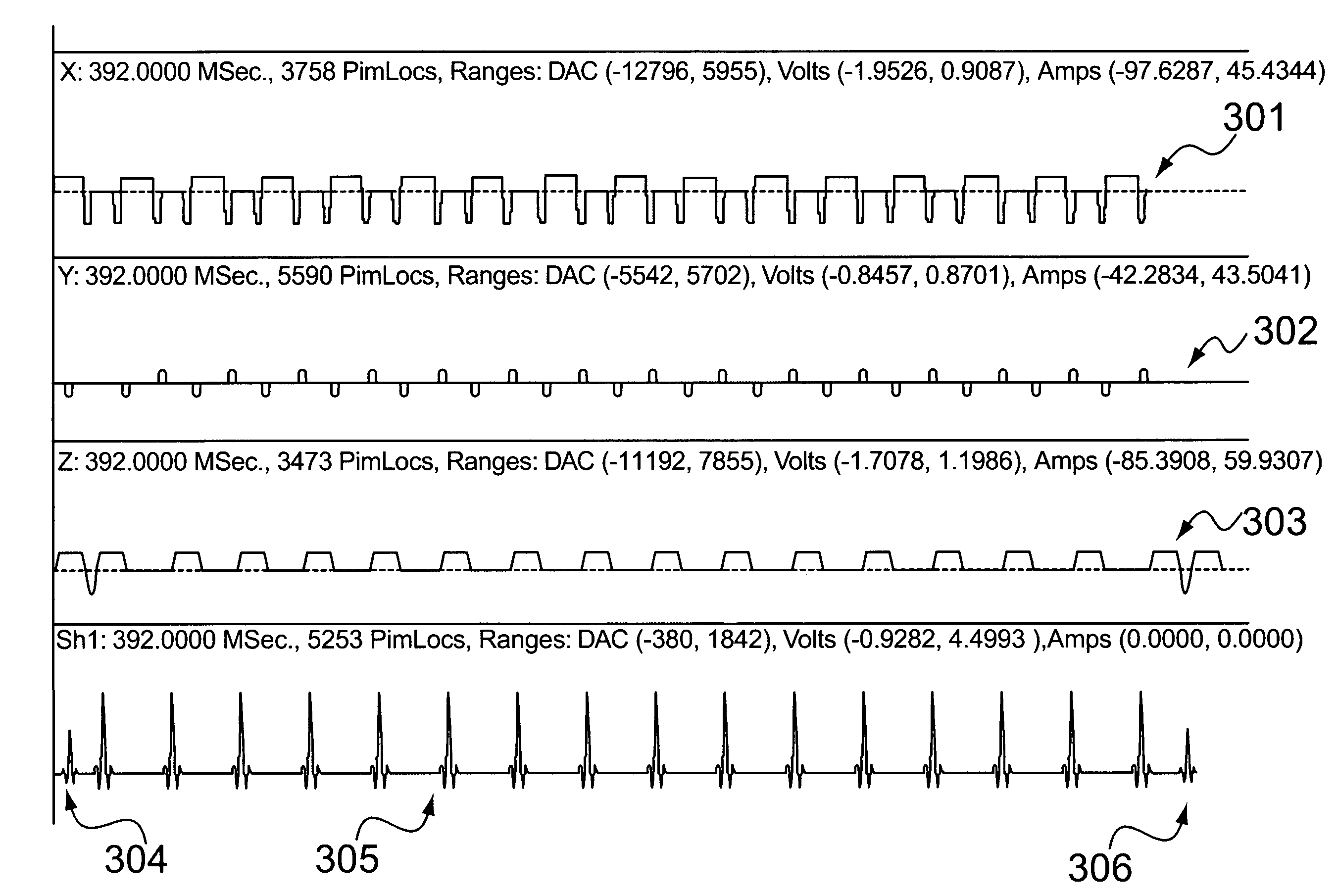
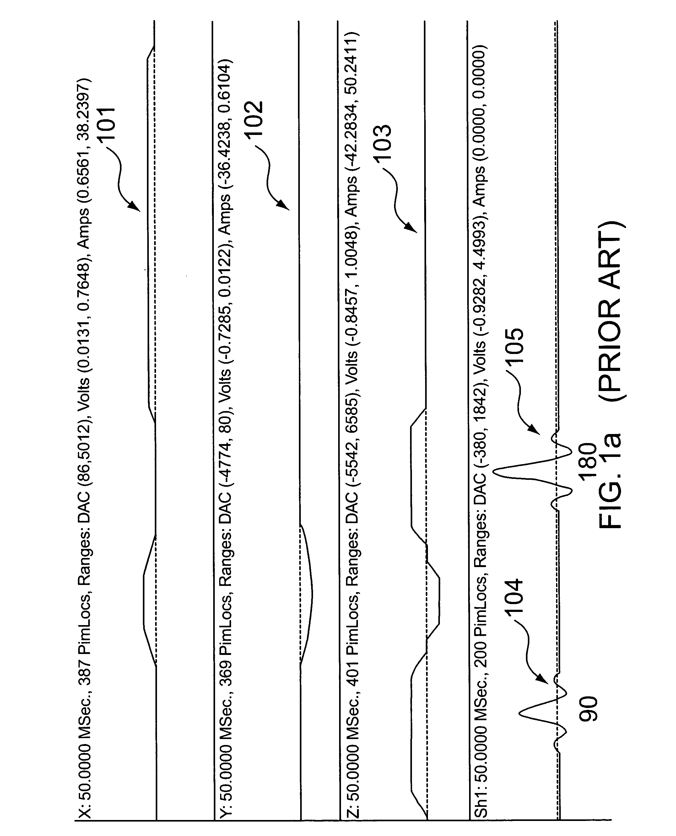
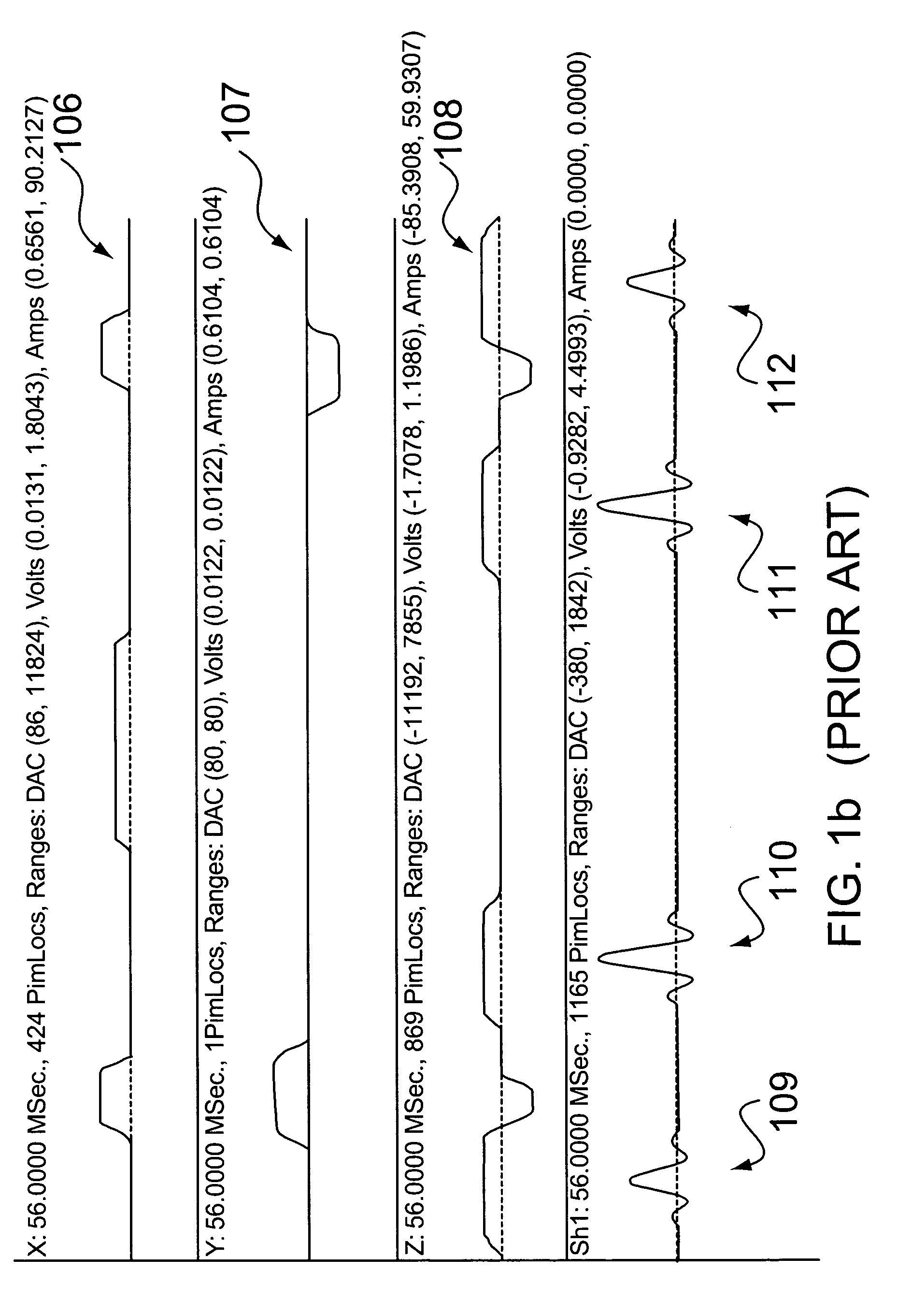
[0032]As noted above, in a conventional spin echo imaging process, data is collected following the 180-degree RF pulse. Prior to each acquisition, the phase-encoding gradient is stepped according to the conventional spin warp imaging technique. The imaging data corresponding to each step of phase-encoding gradient represents a line in the k-space (kx, ky). Once the k-space is filled, a two-dimensional Fourier transform would provide the necessary information to reconstruct an image. A single spin echo pulse sequence is shown in FIG. 1a. As shown, the sequence includes X, Y, and Z gradients 101, 102, 103, and 90-degree and 180-degree RF pulses 104, 105. The single echo sequence can be expanded to a multi-echo sequence by adding a number of subsequent 180-degree pulses. The time gap between the 180-degree pulses is twice that between the 90-degree pulse and the first 180-degree pulse. This train of 180-degree pulses produces echoes at the center of those RF pulses. The T2 dependence o...


PUM


Abstract

An NMR imaging process utilizes application of both a driven equilibrium technique and a fast-spin echo technique to acquire image. The fast-spin echo technique is a multiecho NMR imaging sequence, where different echoes are encoded differently to fill the (kx, kg) space at a speed of 1/n of the single echo speed, where n is the number of echoes in the multiecho sequence. During this echo train, a 90-degree RF pulse applied with proper phase at the center of any echo turns the magnetization back in the direction of the static magnetic field. Within a short waiting time after the 90-degree RF pulse, the spins are ready to be excited again. The multi-echo sequence has one 90-degree RF pulse at the beginning, followed by a series of n 180-degree RF pulses, followed by n echoes. A second 90-degree RF pulse is turned on exactly at the center of the nth echo, which returns all the magnetization left at this time to the static field direction. Only one frequency is used for excitation in acquiring the NMR signal in the single slice mode. Gradients are adjusted for oblique scanning. In the multislice acquisition mode, RF phases of different slices are different from one another and the final images can be constructed either by sharing the kg space or by using a transform process to separate the slices.

Description

CROSS-REFERENCE TO RELATED APPLICATION[0001]This is a continuation of U.S. patent application Ser. No. 09 / 769,446, which was filed on Jan. 26, 2001 now abandoned.FIELD OF THE INVENTION[0002]In general, the present invention relates to methods of performing nuclear magnetic resonance (NMR) imaging. In particular, the present invention is a method of reducing the scan time in performing NMR imaging by utilizing driven equilibrium and fast-spin echo techniques.BACKGROUND OF THE INVENTION[0003]Magnetic resonance imaging (MRI) is one of the most versatile and fastest growing modalities in medical imaging. Since the discovery by Dr. Raymond Damadian in the early 1970s that nuclear magnetic resonance techniques can be used to scan the human body to yield useful diagnostic information, medical NMR imaging devices have been developed for obtaining NMR images of the internal structures of patients. Subsequently, much effort has been expended to improve and refine the techniques used for obtai...

Claims


Application Information

Patent Timeline
IPC IPC(8): G01V3/00
CPCG01R33/5613
Inventor SHENOY, RAJENDRA K.
Owner FONAR
Why Eureka
Try Eureka