Crystal oscillator circuit having a start-up time reduction circuit

a technology of start-up time reduction and crystal oscillator, which is applied in the direction of oscillator generators, pulse automatic control, electrical equipment, etc., can solve the problems of degrading crystal accuracy and reliability, and lack of a mechanism to re-apply extra gain

Active Publication Date: 2006-04-25
NAT SEMICON CORP
View PDF9 Cites 24 Cited by
  • Summary
  • Abstract
  • Description
  • Claims
  • Application Information

AI Technical Summary

Problems solved by technology

Increasing the gain to reduce the start-up time, however, can hasten the aging of the crystal, and hence prematurely degrade the accuracy and reliability of the crystal.
However, one problem with the prior approaches to providing additional gain only during the start-up period is that these prior approaches lack any mechanism to re-apply the extra gain to aid the build up of oscillation if the determination of a “stable” oscillation is incorrect, or for any reason the oscillation is interrupted.

Method used


Image

  • Crystal oscillator circuit having a start-up time reduction circuit
  • Crystal oscillator circuit having a start-up time reduction circuit
  • Crystal oscillator circuit having a start-up time reduction circuit

Examples


Embodiment Construction

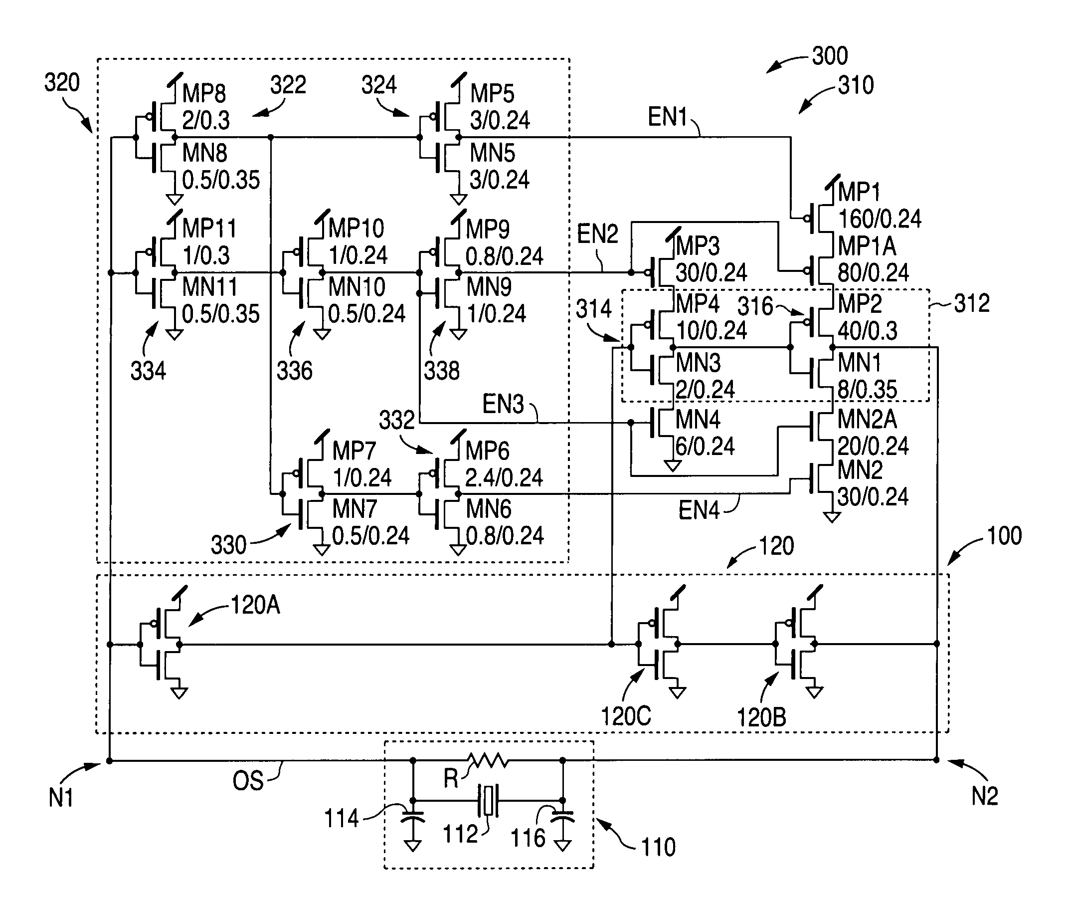
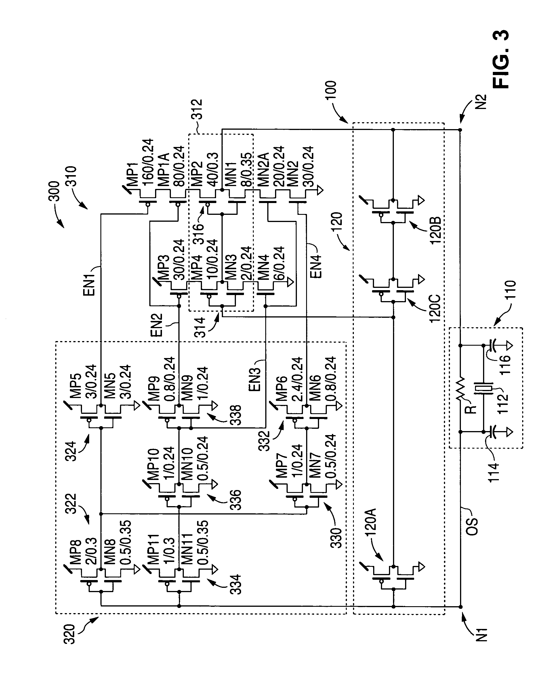
[0021]FIG. 3 shows a schematic diagram that illustrates an example of a quartz-crystal oscillator circuit 300 in accordance with the present invention. As described in greater detail below, crystal oscillator circuit 300 substantially reduces the start-up time by providing additional gain only during the start-up period (when the oscillation is building toward a steady state level).

[0022]In addition, crystal oscillator circuit 300 dynamically monitors the oscillation of circuit 300. As a result, even if the oscillation collapses following the start-up period after the additional gain has been shut off, circuit 300 dynamically responds to the reduction of oscillation and turns on the additional gain again.

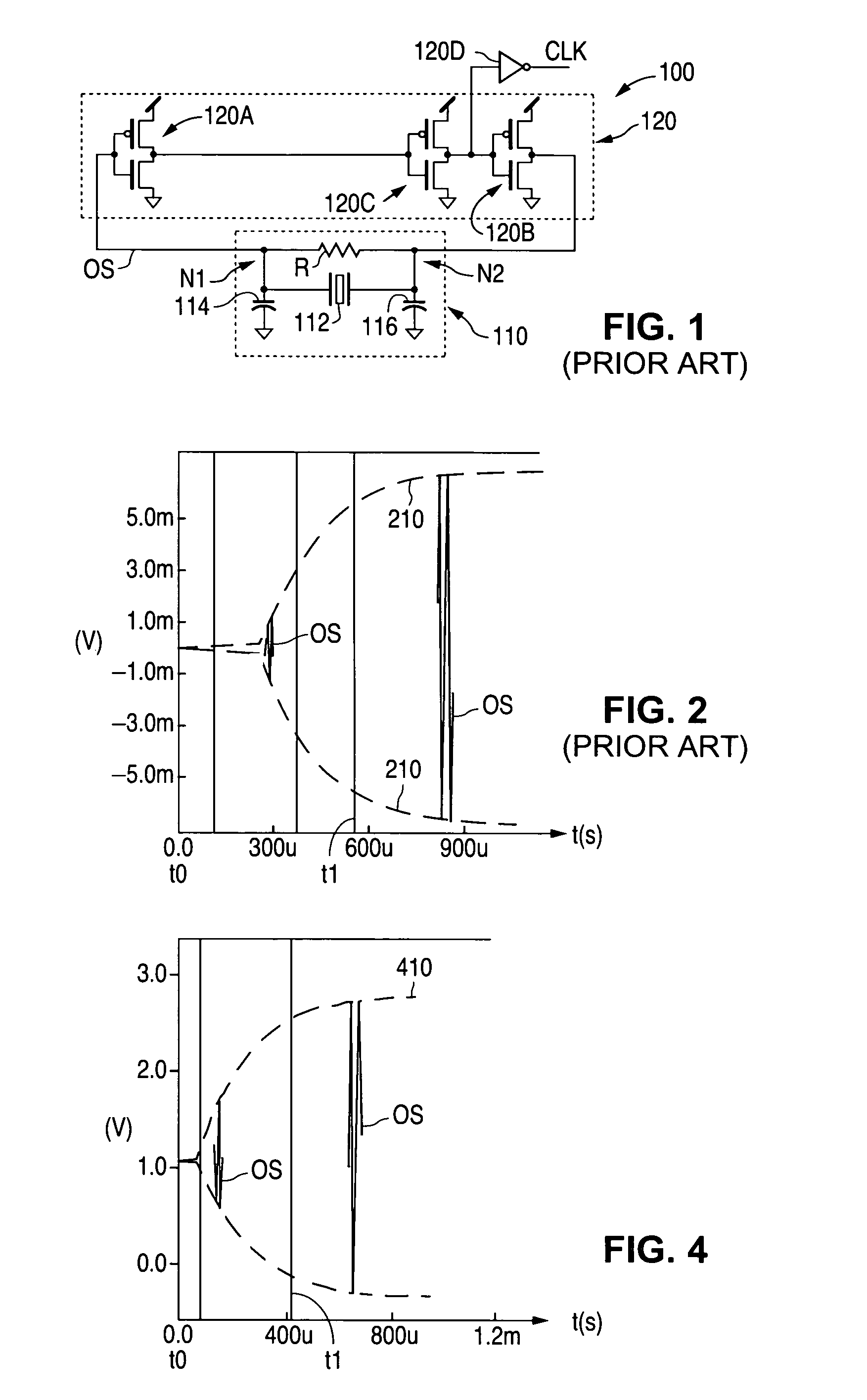
[0023]Crystal oscillator circuit 300 is similar to crystal oscillator circuit 100 and, as a result, utilizes the same reference numerals to designate the structures which are common to both circuits. As shown in FIG. 3, crystal oscillator circuit 300 differs from crystal oscillator ...


PUM


Abstract

A quartz-crystal oscillator circuit substantially reduces the start-up time of the crystal oscillator circuit by utilizing a start-up time reduction circuit that adds additional gain to the crystal oscillator circuit during the start-up period, and removes the additional gain as the oscillator circuit nears steady state operation. Furthermore, the start-up time reduction circuit dynamically monitors the oscillation amplitude. If the build up of oscillation is interrupted, the additional gain will be re-applied.

Description

BACKGROUND OF THE INVENTION[0001]1. Field of the Invention[0002]The present invention relates to crystal oscillator circuits and, more particularly, to a crystal oscillator circuit that has a start-up time reduction circuit.[0003]2. Description of the Related Art[0004]An oscillator is a circuit that outputs a periodic signal. FIG. 1 shows a schematic diagram that illustrates a prior-art, quartz-crystal oscillator circuit 100. As shown in FIG. 1, crystal oscillator circuit 100, which is also known as a Pierce oscillator, includes a crystal circuit 110 that has a quartz crystal 112 and a bias resistor R.[0005]Quartz crystal 112, in turn, has a first terminal that is connected to a first node N1, and a second terminal that is connected to a second node N2. Further, bias resistor R also has a first terminal that is connected to the first node N1, and a second terminal that is connected to the second node N2.[0006]In addition, crystal oscillator circuit 100 includes a first capacitor 114...

Claims


Application Information

Patent Timeline
Patent Type & Authority Patents(United States)
IPC IPC(8): H03B5/32H03L5/00
CPCH03L3/00H03B5/06
Inventor LU, WEIYETSE, THOMASCHAN, WAI CHEONG
Owner NAT SEMICON CORP
Why Eureka
Try Eureka