Soft-start with back bias conditions for PWM buck converter with synchronous rectifier

a synchronous rectifier and back bias technology, applied in the direction of electric variable regulation, process and machine control, instruments, etc., can solve problems such as system failure, and achieve the effect of preventing current reversal (sinking) and efficient preventing the turning

Inactive Publication Date: 2005-01-11
ASTEC INT LTD
View PDF15 Cites 38 Cited by
  • Summary
  • Abstract
  • Description
  • Claims
  • Application Information

AI Technical Summary

Benefits of technology

The present invention solves the problems of prior art devices by providing, in a system comprising a plurality of paralleled converters, a control circuit that efficiently prevents the turning on of the synchronous rectifier in a buck converter during a predetermined condition, so as to prevent current reversing through the synchronous rectifier during that time. In one embodiment, the present invention provides control of the synchronous rectifier during the soft-start time for a non-isolated DC-DC buck converter, thereby preventing current reversing (sinking) during its soft start process. In another embodiment of the present invention, a circuit uses a signal indicative of a soft-start condition for a converter to prevent the turning on of the synchronous rectifier during the soft-start time. The present invention also solves the synchronous rectifier back bias problem during the soft-start of a converter used in a paralleled converter configuration.

Problems solved by technology

The bi-directional current flowing capability of the synchronous rectifier 18 may pose a serious problem when such rectifiers are used in paralleled power converters.
For this exemplary system, because the synchronous rectifier allows reverse current flow, a system failure may result, e.g. from recycling one or more modules while the system is already in operation, and powering on each of paralleled modules at different times, etc.

Method used


Image

  • Soft-start with back bias conditions for PWM buck converter with synchronous rectifier
  • Soft-start with back bias conditions for PWM buck converter with synchronous rectifier
  • Soft-start with back bias conditions for PWM buck converter with synchronous rectifier

Examples


Embodiment Construction

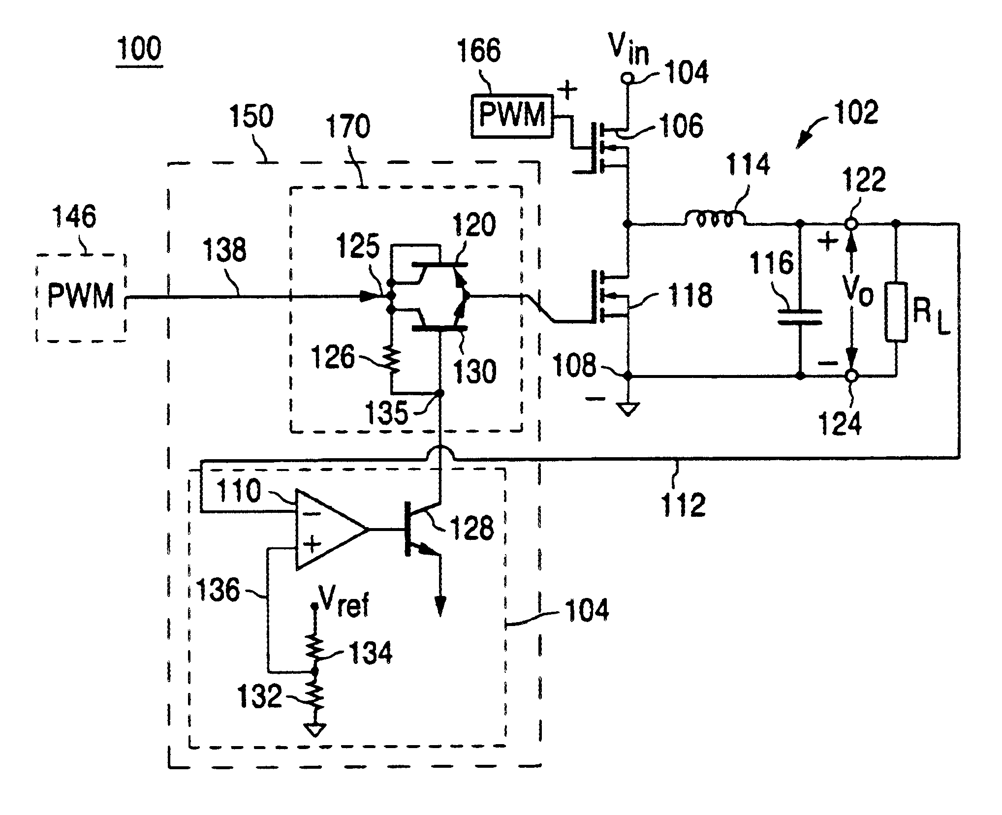
The present invention overcomes the drawbacks of known prior art circuits. A preferred embodiment of the circuit for each converter in a paralleled system of converters is shown in FIG. 5. The converter 200 has an input terminal 104 to which an input DC voltage Vin is coupled relative to ground and an output terminal 122 where the output DC voltage VO of each converter module is provided relative to ground. Converter 200 includes a control circuit 250 coupled to a buck regulator 102 having a synchronous rectifier 118. The buck regulator 102 comprises a switch 106, an inductor 114, and a capacitor 116, connected in a conventional way between input terminal 104 and output terminal 122. An exemplary load RL is shown coupled to the output of converter 200. Switch 106 is typically a power MOSFET which is controlled in a known manner by a PWM 166 that is responsive to the output voltage Vo. When the switch 106 is closed, the capacitor 116 is charged via switch 106 and inductor 114 from th...


PUM


Abstract

A circuit that efficiently prevents the turning on of the synchronous rectifier in a buck converter during a predetermined condition, so as to prevent current reversing through the synchronous rectifier during that time. In one embodiment, the circuit provides control of the synchronous rectifier during the soft-start time for a non-isolated DC-DC buck converter, thereby preventing current reversing (sinking), referred to as the back bias condition, during its soft start process. In another embodiment, a circuit uses a signal indicative of a soft-start condition for a converter to prevent the turning on of the synchronous rectifier during the soft-start time. A corresponding system solves the aforementioned synchronous rectifier back bias problem for converters used in a paralleled converter configuration.

Description

FIELD OF INVENTIONThe present invention relates to power converters, and more particularly, to a circuit that controls synchronous rectifier back bias in non-isolated DC-DC buck converters.BACKGROUND OF THE INVENTIONIncreasingly, synchronous rectifiers are replacing freewheeling diodes in non-isolated DC-DC buck converters in order to increase the power conversion efficiency of the converters. One feature of non-isolated DC-DC converters with synchronous rectification is that current is enabled to flow not only to the output terminals through the synchronous rectifier but also in a reverse direction from the output terminals back into the converter, i.e., a non-isolated dc-dc converter with synchronous rectification can have both current-sourcing and current-sinking capability.A conventional buck converter is shown in FIG. 1. As is well known, a basic buck converter comprises a switch 6, an input filter capacitor 8, a freewheeling diode 12, an inductor 14, and a capacitor 16, connec...

Claims


Application Information

Patent Timeline
Patent Type & Authority Patents(United States)
IPC IPC(8): H02M3/158H02M3/04H02M1/00
CPCH02M3/1588H02M1/32H02M1/36Y10S323/901Y02B70/1466Y02B70/10
Inventor HUANG, HONGYOUNG, CHRIS M.
Owner ASTEC INT LTD
Why Eureka
Try Eureka