
Multi-band wide-angle scan phased array antenna with novel grating lobe suppression

a phased array antenna and wide-angle scan technology, applied in the direction of resonant antennas, particular array feeding systems, radiating elements structural forms, etc., can solve the problems of difficult implementation of multiple bands of antennas employing reflector technology such as parabolic reflectors, limited interlaced arrays, and difficult to obtain three and four band operation for current applications. , to achieve the effect of minimizing mechanical blockage and mutual coupling

Active Publication Date: 2006-04-25
ROCKWELL COLLINS INC
View PDF4 Cites 85 Cited by
  • Summary
  • Abstract
  • Description
  • Claims
  • Application Information

AI Technical Summary

Benefits of technology

[0015]It is an advantage of the present invention to minimize mechanical blockage and mutual coupling from one frequency band to another in a multi-band phased array antenna.
to minimize mechanical blockage and mutual coupling from one frequency band to another in a multi-band phased array antenna.

Problems solved by technology

Interlaced arrays are limited in the number bands of operation where three and four band operation needed for current applications is difficult to obtain.
Antennas employing reflector technology such as parabolic reflectors are difficult to implement in multiple bands.
Furthermore, such antennas typically have slow mechanical beam scanning making it difficult to track a communications satellite in a rapidly maneuvering vehicle.
Lens antennas are difficult to implement in multi-band designs.
Previous phased arrays have been limited in bandwidth.
Efficient broadband radiating elements tend to be large thereby making an entire phased array too large for many applications.

Method used


Image

  • Multi-band wide-angle scan phased array antenna with novel grating lobe suppression
  • Multi-band wide-angle scan phased array antenna with novel grating lobe suppression
  • Multi-band wide-angle scan phased array antenna with novel grating lobe suppression

Examples


Embodiment Construction

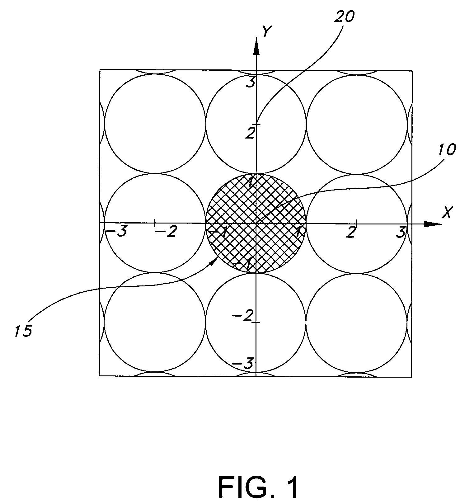
[0026]The present invention is for a multi-band wide-angle scan phased array antenna architecture with a novel implementation for superimposing / suppressing grating lobes for narrow beam phased array applications such as communications, radar, and electronic surveillance systems.

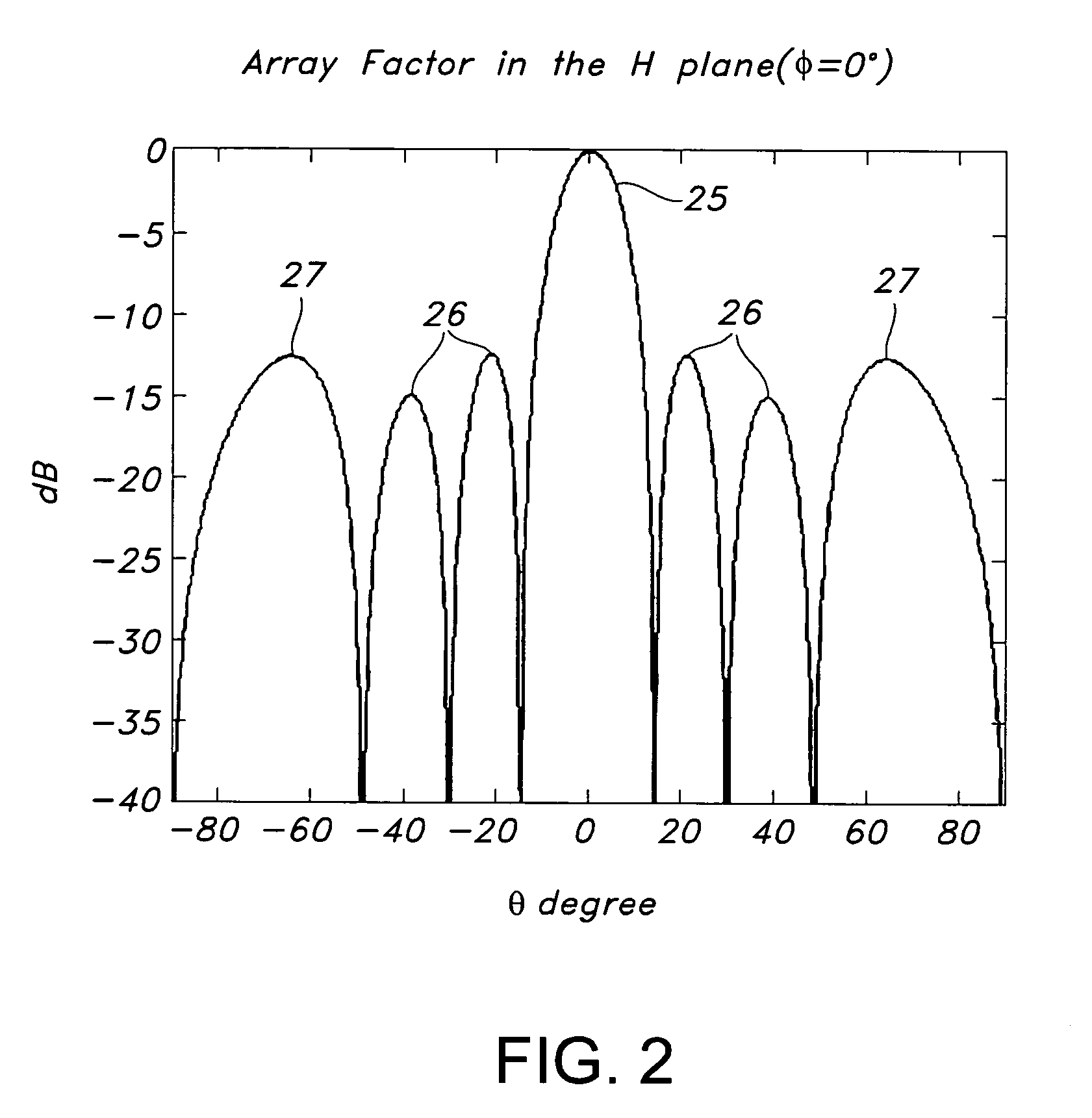
[0027]It is well known within the art that the operation of a phased array is approximated to the first order as the product of the array factor and the radiation element pattern as shown in Equation 1 for a linear array. This analysis may be readily extended to a two-dimensional array as well.

[0028]EA⁡(θ)≡Ep⁡(θ,ϕ)︸Radiation⁢⁢Element⁢⁢Pattern⁢⁢[exp⁡(-j⁢2⁢π⁢⁢roλ)ro]︸Isotropic⁢⁢Element⁢⁢Pattern·∑N⁢An⁢exp⁡[-j⁢2⁢πλ⁢n⁢⁢Δ⁢⁢x⁡(sin⁢⁢θ-sin⁢⁢θo)]︸Array⁢⁢FactorEquation⁢⁢1

[0029]Standard spherical coordinates are used in Equation 1 and θ is the scan angle referenced to bore sight of the array. Introducing phase shift at all radiating elements within the array changes the argument of the array factor exponential term in Eq...


PUM


Abstract

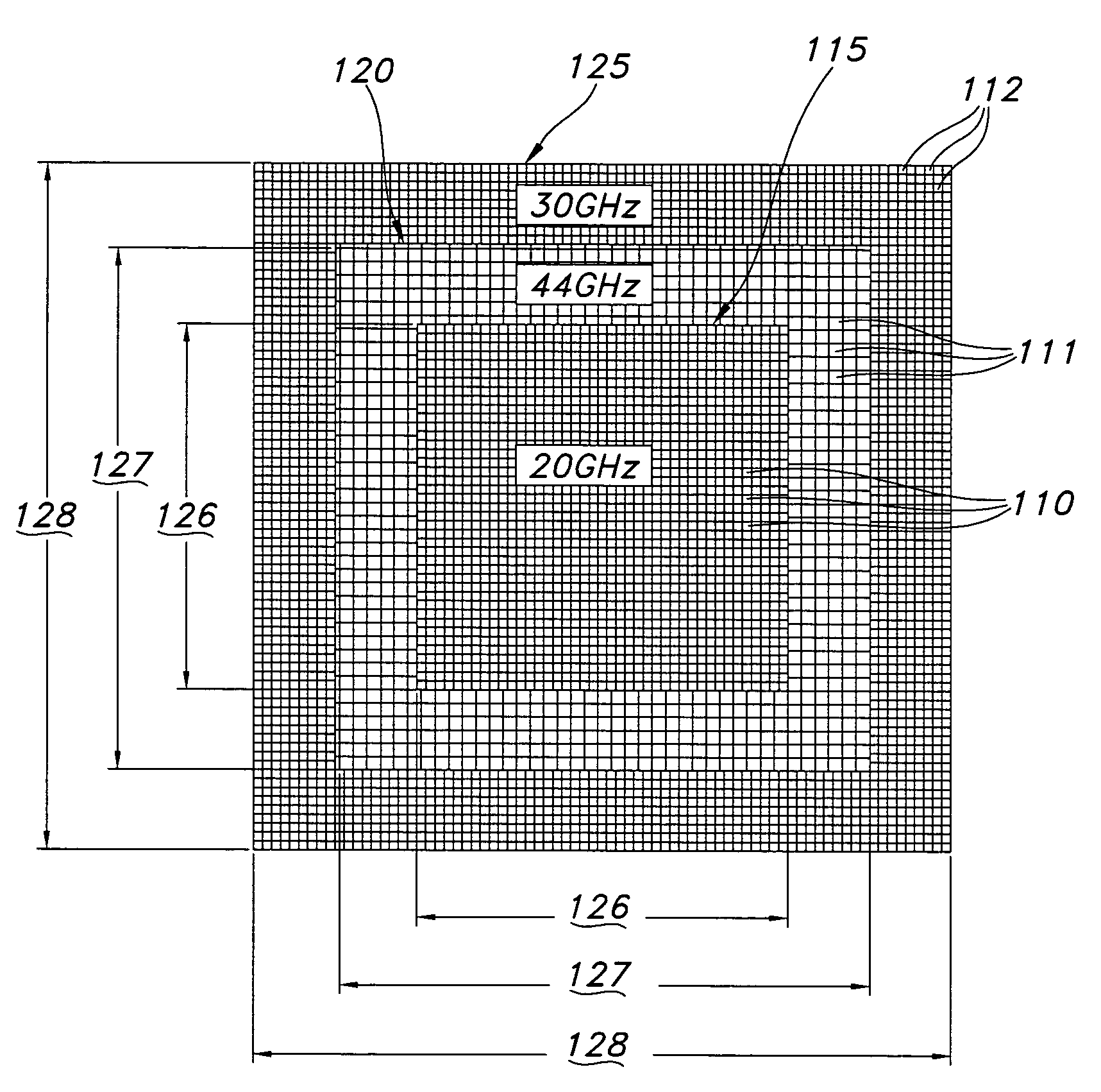
A multi-band wide-angle scan phased array antenna with novel grating lobe suppression has a first plurality of radiation elements for radiating a first frequency arranged in a rectangular configuration. A second plurality of radiation elements for radiating second frequency are arranged in a rectangular frame around the first radiation elements. A third plurality of radiation elements for radiating third frequency are arranged in a rectangular frame around the second radiation elements. The radiation elements are apertures that are λ / 2 of an operating frequency in size. The radiation elements may also be arranged in square, circular, or elliptical configurations.

Description

CROSS REFERENCE[0001]Related U.S. patent application Ser. No. 10 / 141,269, “Multiband Phased Array Antenna Utilizing A Unit Cell”, by James B. West and Mohamed Wajih A. Elsallal, now U.S. Pat. No. 6,650,291, is hereby incorporated by reference.BACKGROUND OF THE INVENTION[0002]This invention relates to antennas, phased array antennas, and specifically to a multi-band, wide-angle scan, and narrow beamwidth phased array antenna with grating lobe suppression.[0003]Over the last four decades, much effort has been given to the development of methods to scan reflector antennas through large angles. Techniques for shaping the reflector to compensate for the distortion caused by scanning have been investigated as disclosed in “Wide-Angle Scanning with Reflector Antennas: a New Design Technique”, IEEE National Aerospace and Electronics Conference, 2000, pp. 136–145. The technological challenges to cancel sidelobes and suppress clutter are known.[0004]Previous attempts to provide antennas with ...

Claims


Application Information

Patent Timeline
Patent Type & Authority Patents(United States)
IPC IPC(8): H01Q1/38
CPCH01Q21/0006H01Q5/42H01Q5/28H01Q21/061
Inventor ELSALLAL, MOHAMED WAJIH A.WEST, JAMES B.
Owner ROCKWELL COLLINS INC
Learn More