Linked network switch configuration

a network switch and configuration technology, applied in data switching networks, multiplex communication, digital transmission, etc., can solve the problems of design requirements becoming more and more complex, design constraints,

Inactive Publication Date: 2006-04-25
AVAGO TECH INT SALES PTE LTD
View PDF72 Cites 34 Cited by
  • Summary
  • Abstract
  • Description
  • Claims
  • Application Information

AI Technical Summary

Problems solved by technology

As speed has increased, design constraints and design requirements have become more and more complex with respect to following appropriate design and protocol rules and providing a low cost, commercially viable solution.

Method used


Image

  • Linked network switch configuration
  • Linked network switch configuration
  • Linked network switch configuration

Examples


Embodiment Construction

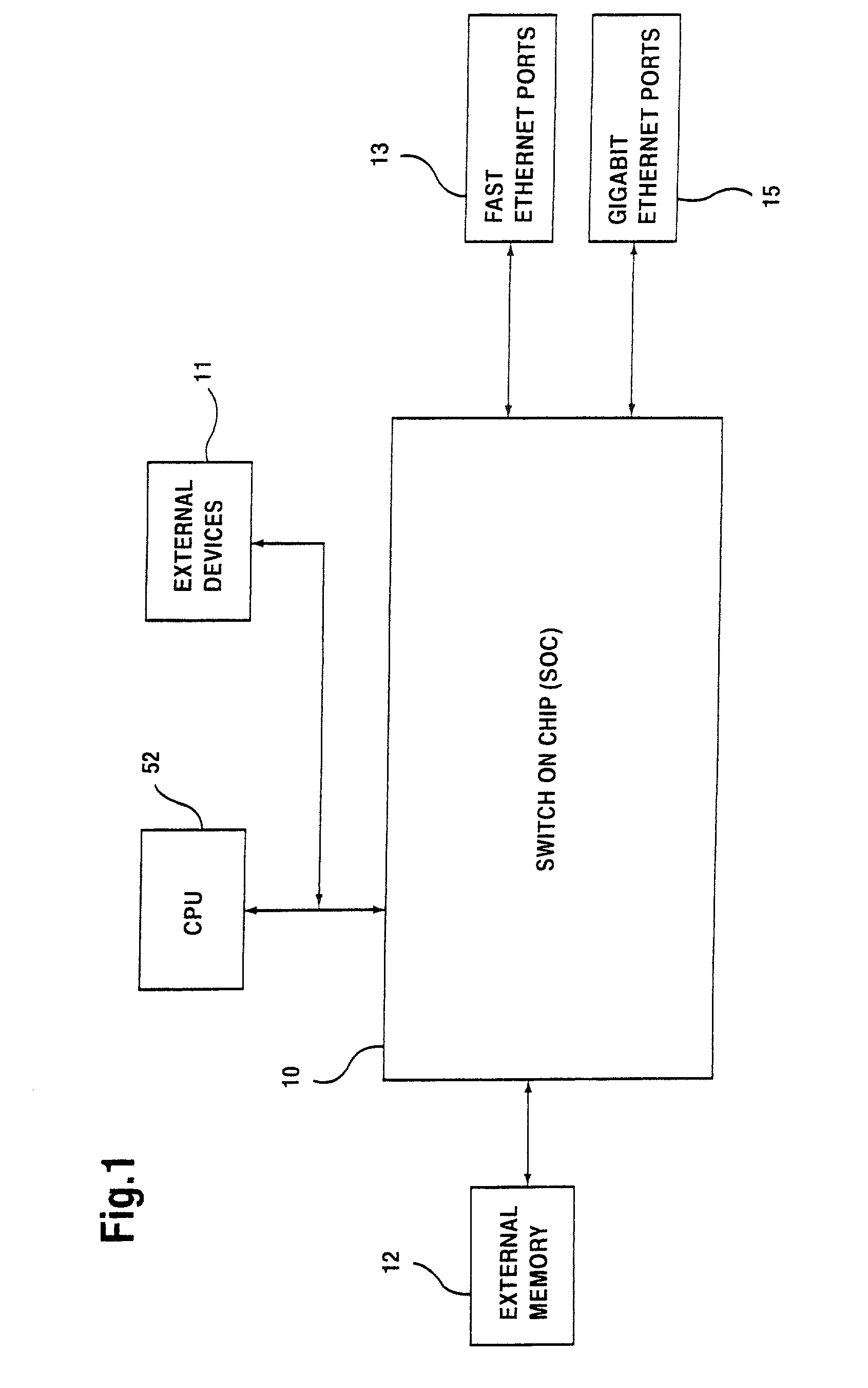
[0060]FIG. 1 illustrates a configuration wherein a switch-on-chip (SOC) 10 is functionally connected to external devices 11, external memory 12, fast ethernet ports 13, and gigabit ethernet ports 15. For the purposes of this discussion, fast ethernet ports 13 will be considered low speed ethernet ports, since they are capable of operating at speeds ranging from 10 Mbps to 100 Mbps, while the gigabit ethernet ports 15, which are high speed ethernet ports, are capable of operating at 1000 Mbps. External devices 11 could include other switching devices for expanding switching capabilities, or other devices as may be required by a particular application. External memory 12 is additional off-chip memory, which is in addition to internal memory which is located on SOC 10, as will be discussed below. CPU 52 can be used as necessary to program SOC 10 with rules which are appropriate to control packet processing. However, once SOC 10 is appropriately programmed or configured, SOC 10 operates...


PUM


Abstract

A network device includes a first switch, a second switch, and a CPU. The first and second switches each include a group of ports numbered by a numbering scheme, a rate control logic for performing rate control functions related to switching data packets between the network ports, and a local communications channel for transmitting messages between the group of ports and the rate control logic. Each switch is configured to generate rate control messages based on data packet traffic to its group of ports. The CPU is coupled to the first switch and the second switch and configured to control the first switch and the second switch. A first link port of the first switch is coupled to a second link port of the second switch, and the first link port and the second link port are configured to relay the rate control messages to each other.

Description

REFERENCE TO RELATED APPLICATIONS[0001]This application claims priority of U.S. Provisional Patent Application Ser. No. 60 / 247,907 entitled “Using MAC Control Frame to Relay Rate Control Information Across Dual Chip System,” filed on Nov. 14, 2000, Application Ser. No. 60 / 247,906 entitled “Address Learning and Forwarding Scheme on Inter Chip Link on Dual Chip System,” filed on Nov. 14, 2000, Application Ser. No. 60 / 247,920 entitled “Smart Ingress to Enable Rate Control Capability at the Inter Chip Link on Dual Chip Switch,” filed on Nov. 14, 2000, and Application Ser. No. 60 / 247,921 entitled “Self-Contained HOL Handling on Inter Chip Link,” filed on Nov. 14, 2000. The contents of these provisional applications are hereby incorporated by reference.BACKGROUND OF THE INVENTION[0002]1. Field of the Invention[0003]The invention relates to systems and methods for high performance network switching. In particular, the invention relates to a new switching architecture for integrating multip...

Claims


Application Information

Patent Timeline
Patent Type & Authority Patents(United States)
IPC IPC(8): H04J3/24H04L12/56
CPCH04L12/5601H04L45/583H04L47/10H04L47/15H04L47/263H04L47/266H04L47/522H04L47/623H04L49/109H04L49/351H04L49/606H04L49/90H04L49/901H04L12/5693H04L2012/5621H04L49/205H04L49/206H04L49/3009H04L47/50H04L47/43
Inventor TZENG, SHRJIE
Owner AVAGO TECH INT SALES PTE LTD
Why Eureka
Try Eureka