Data center path switch with improved path interconnection architecture

a path switch and path interconnection technology, applied in the field of data center path switches, can solve the problems of complex computer system operation and maintenance, data center operation and maintenance is typically very expensive, and the average time for data center operation and maintenance is 500 nsec per second

Active Publication Date: 2016-01-07
FIBER MOUNTAIN INC
View PDF19 Cites 182 Cited by
  • Summary
  • Abstract
  • Description
  • Claims
  • Application Information

AI Technical Summary

Benefits of technology

[0033]Preferably, the path interconnection architecture used in the data center path switch according to the present application is capable of scaling to several thousand ports with equivalent reliability and performance and can be designed as a modular architecture.
[0034]In an alternate embodiment, the

Problems solved by technology

Early computer systems were complex to operate and maintain, and required a special environment in which to operate.
However, data centers are typically very expensive to build, operate and maintain, and data center operators are searching for ways to reduce costs while increasing data processing and transmission capabilities, while meeting all reliability requirements.
The current state of packet switches has latency issues of about and in excess of 500 nsec per packet, which is insufficient for today's data centers.
For a very large number of ports, data center network switch cores have to be configured in hierarchical or mesh configurations, which adds complexity to the network, decreases reliability, and further increases latency.
However, today's demand for higher port counts in data center path switches restricts the above path switching techniques that may be employed to achieve high density, high speed path switching.
Factors associated with such path switching techniques, such as high cost, low manufacturing yield, low reliability, high data latency, signal loss, power consumption, heat dissipation, and real estate, have heretofore prevented the expansion of path switching in today's high speed, high density data center data center path switches.
However, MEMS for example, has low reliability due to moving parts (e.g., mirrors), and requires corrective circuitry to ensure accurate beam alignment

Method used


Image

  • Data center path switch with improved path interconnection architecture
  • Data center path switch with improved path interconnection architecture
  • Data center path switch with improved path interconnection architecture

Examples


Embodiment Construction

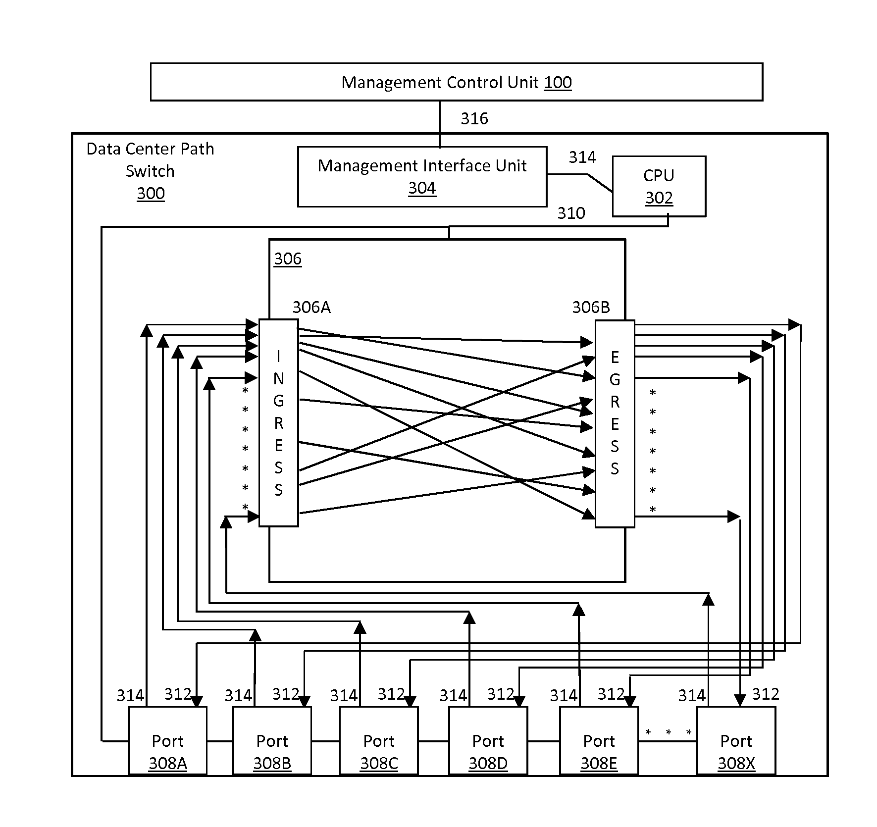
[0048]Referring now to FIG. 3, an exemplary architecture of the path switch 300 according to the present application is provided. In this embodiment, the path switch 300 includes a set of ports 308, path interconnection unit 306, management interface unit 304 and CPU 302. The number of ports 308 and the bandwidth per port of the set of ports 308 is generally set by the capability of the path interconnection unit 306. Preferably, the ports are transceiver ports capable of receiving Physical Layer signals from various mediums, converting the signals into a form that can be routed by the path interconnection unit 306, and converting signals from the form routed by the path interconnection unit 306 to a form for transmission as a Physical Layer signal through a port 308 onto an external medium capable of handling such Physical Layer signal. The configuration of the data center path switch is such that the latency between an input port and an output port is less than 500 nsec, and prefer...


PUM


Abstract

A data center path switch architecture permits path switching of the signal path of incoming signals to one or more output paths in real time without the need for manual intervention, and without delays associated with current data center network switches. In this architecture, a switching core capable of switching signals directly from the ingress of the switching core to alternate destination ports in real time, either under software or hardware control.

Description

CROSS-REFERENCE TO RELATED APPLICATIONS[0001]This application claims priority to U.S. Provisional Application No. 62 / 020,894, filed on Jul. 3, 2014, entitled “Data Center Path Switch With Improved Path Interconnection Architecture” which is incorporated herein in its entirety by reference.BACKGROUND[0002]1. Field[0003]The present disclosure relates generally to data center path switches typically used in data centers of enterprise networks and service provider networks, and more particularly to high density data center path switches having the capability of switching entire data paths with low latency path interconnections between input ports and the output ports.[0004]2. Description of the Related Art[0005]Telecommunication switching has a long history, evolving from manual switching to early automatic electro-mechanical switching systems, such as step-by-step switching systems and crossbar switching systems, to more recent electronic and optical switching systems.[0006]Digital and...

Claims


Application Information

Patent Timeline
IPC IPC(8): H04Q11/00
CPCH04Q11/0062H04Q11/0003H04Q2011/0039H04Q2011/005H04Q2011/0056H04Q2011/0058H04L49/356H04L49/1515H04L49/358H04L49/253H04Q11/0005
Inventor RAZA, MOHAMMAD H.STONE, DAVID G.LORENZO, ARISTITOPLANTE, RONALD M.LAGANA, JOHN R.
Owner FIBER MOUNTAIN INC
Why Eureka
Try Eureka