

Two dimensional data eye centering for source synchronous data transfers
- Summary
- Abstract
- Description
- Claims
- Application Information
AI Technical Summary
Problems solved by technology
Method used
Image

Examples
Embodiment Construction
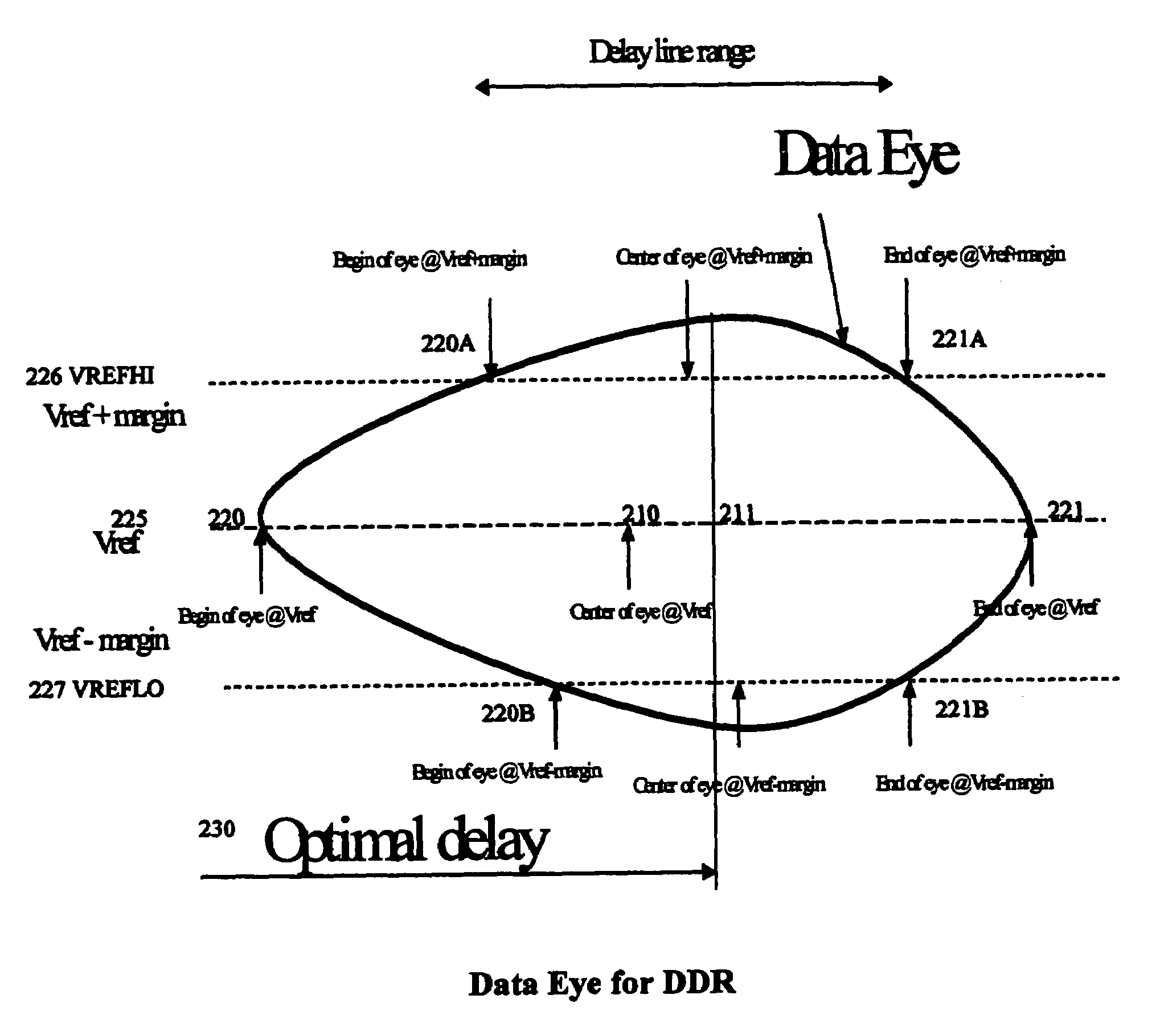
[0023]Data transfers are referred to as source synchronous when the clock (or strobe) signal that latches the data is supplied by the same chip (a driver) that is driving the data. With source synchronous data transfers, the same process, temperature, and voltage variations affect both the data and clock timings, and a multi-chip system may not need additional timing margin to account for independent variation in these variables along the clock and data paths.
[0024]Strobe signals are clock signals that are transmitted with data signals, either simultaneously or after a predetermined delay. The strobe signal is used to time-synchronize data appearing as input signals at a receiver from a driver (transmitter). The use of the strobe signal to indicate when data should be sampled avoids using a clock which is sent to both driver and receiver. If this latter technique is used, then the skew between the two versions of the clock (transmitter and receiver) must be added to the time that ea...
PUM
 Abstract
Description
Claims
Application Information