Ventilator breath display and graphic user interface

a graphic user interface and ventilator technology, applied in the direction of user interface execution, local control/monitoring, instruments, etc., can solve the problem of limiting the opportunity to select incorrect settings

Inactive Publication Date: 2006-05-02
NELL COR PURITAN BENNETT INC (US)
View PDF23 Cites 218 Cited by
  • Summary
  • Abstract
  • Description
  • Claims
  • Application Information

AI Technical Summary

Benefits of technology

[0011]Briefly, and in general terms, the present invention is directed to a graphic user interface system for controlling a computer controlled ventilator to provide respiratory therapy to a patient. In a broad aspect of the invention, the invention includes a digital processor, a touch sensitive display screen and entry means cooperating to provide a user-friendly graphic interface for use in setting up and carrying out a wide variety of respiratory therapies. The processor controls the displaying of a plurality of screens, including user selectable graphic on-screen buttons for setting the values of various ventilator operating parameters for controlling the ventilator. Depending on the on-screen button touched, the processor causes different graphics to be displayed on the screens, provides graphic representations of the effect on the overall respiratory strategy caused by changes to the settings, and may also provide displays of patient data, alarm conditions, and other information.
[0012]In one preferred embodiment of the invention, the system includes the use of a digitally encoded knob for altering selected and displayed values of ventilation parameters, with the acceptable values indicated and unacceptable values alarmed and / or limited to prevent harm to the patient. The digital encoded rotation of the knob may be analyzed by the processor and a magnification factor applied to the knob output to increase the speed with which displayed values are altered. The magnification factor may also be used in the event of an overshoot condition to assist a user in recovering from the overshoot.
[0016]In another presently preferred embodiment of the invention, the user is provided a graphic interface in which the user is allowed to view and adjust a variety of alarm limits and is able to vary the levels at which the alarms are set off, within limits that are preset by the programming of the microprocessor as representative of values that are not to be exceeded, either as a function of ideal body weight or general parameters for all patients. The resultant setting of a filtered set of alarms may then be used by the user to avoid the setting of parameters that are likely to result in patient distress or other problems with the therapy, while still allowing the sophisticated user to configure a therapy that is customized for the particular patient.
[0017]In one presently preferred embodiment, the invention also allows the user an “undo” option in which a previously successful setting is reestablished after the user realizes that a series of proposed changes are likely to unworkable for the patient.
[0019]In a further currently preferred embodiment of the invention, the processor allows the user to configure the graphic user interface to provide a display of the current and / or proposed breath parameters and a graphic representation of the breath timing controlled by those parameters. Such a display allows the visualization of relationships between breath parameters, and, while parameters are being changed, provides the user with a visual representation of the effect of the proposed changes on the ventilation strategy while simultaneously allowing the user to view current settings, thus allowing the user to simultaneously view “where they are now” and “where they are going to be.”
[0020]From the above, it may be seen that the present invention represents a quantum leap forward in the user interface available for patient ventilation. While assisting the sophisticated user in both visualizing the ventilation strategy and performance of the patient on the ventilator, it also guides and controls the less sophisticated user in setup and understanding of the relationships between ventilator settings. The invention provides these benefits while enforcing fail-safe functioning in the event of a variety of inadvertent or erroneous settings or circumstances.

Problems solved by technology

The ranges of values of the appropriate settings, or bounds of the ventilation, may be limited by the processor in response to the selected mode of ventilation such that only those values determined to be appropriate are displayed, thus limiting the opportunity to select incorrect settings.

Method used


Image

  • Ventilator breath display and graphic user interface
  • Ventilator breath display and graphic user interface
  • Ventilator breath display and graphic user interface

Examples


Embodiment Construction

[0038]The present invention provides a sophisticated graphic user interface and ventilator breath display capability that allows great flexibility in the setup of the ventilator and visualization of the effect that proposed changes to the ventilator setup may have on the ventilation strategy. More particularly, the invention provides a graphic representation of a breath cycle that allows the user to visually evaluate the effect of such changes, and also to select among appropriate parameters a parameter to “lock” and hold constant while other parameters are changed.

[0039]The drawings will now be described in more detail, wherein like referenced numerals refer to like or corresponding elements among the several drawings.

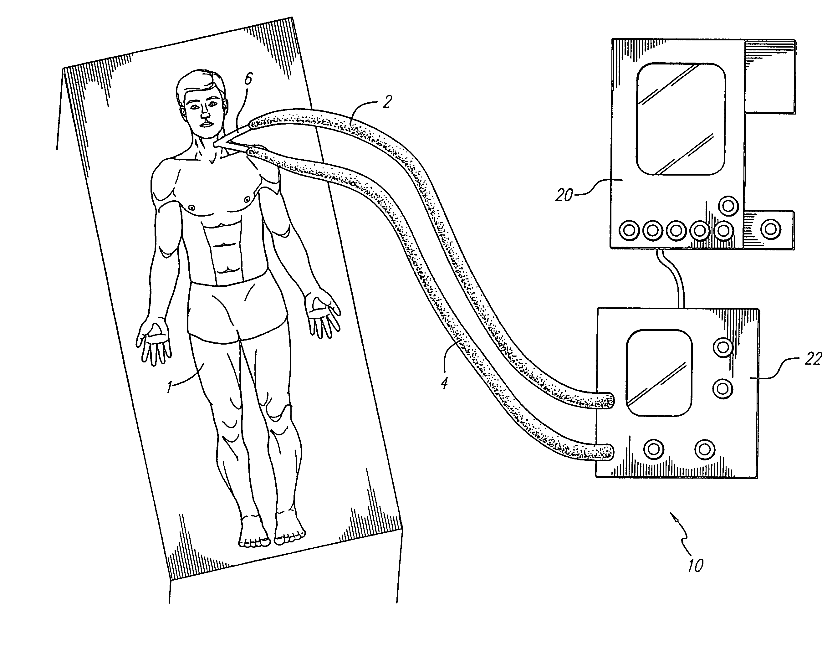
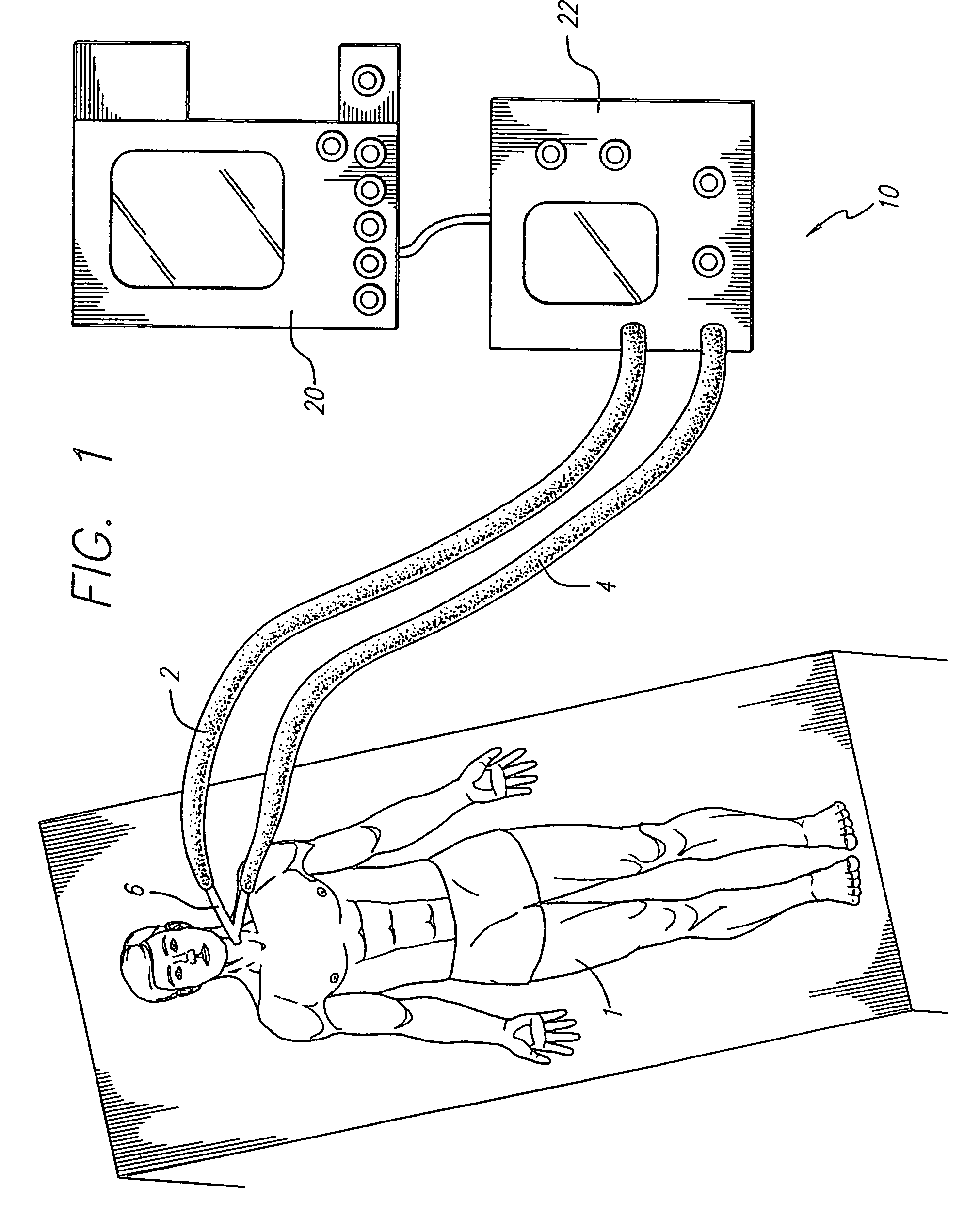
[0040]FIG. 1 shows a patient 1 receiving respiratory therapy from a ventilator system 10 having a graphic user interface 20 connected to and controlling a breath delivery unit, or respirator 22. The patient is connected to the respirator 22 by a patient circuit compri...


PUM


Abstract

The invention is directed to a ventilation control system for controlling the ventilation of a patient. The ventilation control system utilizes a user-friendly user interface for the display of patient data and ventilator status. The user interface includes a graphic representation of a breath cycle that displays the breath cycle currently being ventilated, and is also responsive to changes in ventilation settings to assist the user in evaluation the effect of those changes on the ventilator strategy before the changes are implemented.

Description

RELATED APPLICATIONS[0001]This is a continuation of Ser. No. 09 / 882,200 filed Jun. 15, 2001, now U.S. Pat. No. 6,675,801, which is a continuation of Ser. No. 09 / 253,387 filed Feb. 19, 1999, now U.S. Pat. No. 6,269,812, which is a continuation of Ser. No. 08 / 818,807 filed Mar. 14, 1997, now U.S. Pat. No. 5,881,723.BACKGROUND OF THE INVENTION[0002]1. Field of the Invention[0003]This invention relates generally to the field of medical equipment for respiratory therapy and more specifically to the user interface for a ventilator used for monitoring and controlling the breathing of a patient.[0004]2. Description Of The Related Art[0005]Modern patient ventilators are designed to ventilate a patient's lungs with breathing gas, and to thereby assist a patient when the patient's ability to breathe on his own is somehow impaired. As research has continued in the field of respiration therapy, a wide range of ventilation strategies have been developed. For example, pressure assisted ventilation...

Claims


Application Information

Patent Timeline
Patent Type & Authority Patents(United States)
IPC IPC(8): A61M16/00A61B5/08
CPCA61M16/0051G06F19/3406A61M2205/13A61M2205/505Y10S715/965A61M2205/583A61M2205/587A61M2205/581A61M16/024G16H40/63G06F9/453Y02A90/10G06F3/04842G06F3/0482
Inventor WALLACE, CHARLES L.SANBORN, WARREN G.ARNETT, DAVIDBUTTERBRODT, JAYFERGUSON, HOWARD L.
Owner NELL COR PURITAN BENNETT INC (US)
Why Eureka
Try Eureka