Method for the contactless detection of the position of a butterfly valve shaft of a butterfly valve connecting piece and butterfly valve connecting piece

a technology of butterfly valve and connecting piece, which is applied in the direction of valve operating means/release devices, instruments, machines/engines, etc., can solve the problem that the precision of magnetoresistive sensor elements is not sufficient, and achieve the effect of high precision and unacceptable linearity errors

Inactive Publication Date: 2006-05-02
CONTINENTAL AUTOMOTIVE GMBH
View PDF20 Cites 46 Cited by
  • Summary
  • Abstract
  • Description
  • Claims
  • Application Information

AI Technical Summary

Benefits of technology

[0011]The invention is based here on the idea that a method which particularly reliably ensures detection of a rotary movement of a butterfly valve shaft of approximately 90°, even over particularly long time periods, should detect the respective current position of the butterfly valve shaft in a contactless fashion. This is possible by means of a sensor which comprises a magnetoresistive sensor element. However, this magnetoresistive sensor element does not have the necessary precision when detecting the position of the butterfly valve shaft. The precision of the detection can be increased by virtue of the fact that, instead of a single magnetoresistive sensor element, a second magnetoresistive sensor element is arranged in relation to the first magnetoresistive sensor element. If these two sensor elements then output approximately the same signal but with a phase shift, the current position of the butterfly valve shaft can be detected particularly precisely using the phase shift which can be determined comparatively precisely. For this purpose, a first and a second magnetoresistive sensor element are positioned in relation to a magnet which is arranged on the butterfly valve shaft, an approximately arctan-shaped signal, which characterizes the position of the butterfly valve shaft with sufficient precision, being capable of being generated from the signal of the first magnetoresistive sensor element and from the signal of the second magnetoresistive sensor element. The approximately arctan-shaped signal is independent of temperature here, whereas the amplitudes of the signals of the first magnetoresistive sensor element and of the second magnetoresistive sensor element are temperature-dependent.
[0012]The scaling (amplification, offset) of the sensor by means of an additional pin of the evaluation electronics is advantageously performed using a serial protocol, data for setting the characteristic curve being stored in a nonvolatile memory. This reduces the number of electronic components to a single one, a printed circuit board not being absolutely necessary.
[0013]The signal of the first magnetoresistive sensor element is advantageously subjected to plausibility checking with the signal of the second magnetoresistive sensor element. If a predefined plausibility condition is infringed, a signal is output which is recognizably outside the customary working range. As a result, a redundant embodiment of a first and second sensor, which is otherwise customary for safety reasons, can be dispensed with, making the method particularly easy to handle.
[0016]It is advantageous if the magnet has diametrical magnetization. This results in a more homogenous field, as a result of which relatively large degrees of eccentricity between the sensor head and the magnet axis are acceptable without this leading to an unacceptable linearity error. As a result, the method mentioned above can be carried out particularly reliably even when there are structurally unavoidable imprecisions in the positioning between the magnet and the sensor.
[0020]The evaluation electronics for setting the characteristic curve using a serial protocol advantageously comprise a pin. As a result, it is possible to dispense with a multiplicity of electrical components which would otherwise be necessary as an alternative to setting the characteristic curve.
[0023]The advantages which are achieved with the invention comprise, in particular, the fact that the method for detecting the position of the butterfly valve shaft operates in a contactless fashion and at the same time a degree of precision which is sufficient for detecting the position of the butterfly valve shaft is reliably ensured even over particularly long time periods. In this process, the signals of the first sensor element and of the second sensor element are detected simultaneously and also used for a plausibility checking means which transmits a corresponding signal to the control electronics in the case of a fault.

Problems solved by technology

However, this magnetoresistive sensor element does not have the necessary precision when detecting the position of the butterfly valve shaft.

Method used


Image

  • Method for the contactless detection of the position of a butterfly valve shaft of a butterfly valve connecting piece and butterfly valve connecting piece
  • Method for the contactless detection of the position of a butterfly valve shaft of a butterfly valve connecting piece and butterfly valve connecting piece
  • Method for the contactless detection of the position of a butterfly valve shaft of a butterfly valve connecting piece and butterfly valve connecting piece

Examples


Embodiment Construction

[0032]Corresponding parts are provided with the same reference symbols in all the figures.

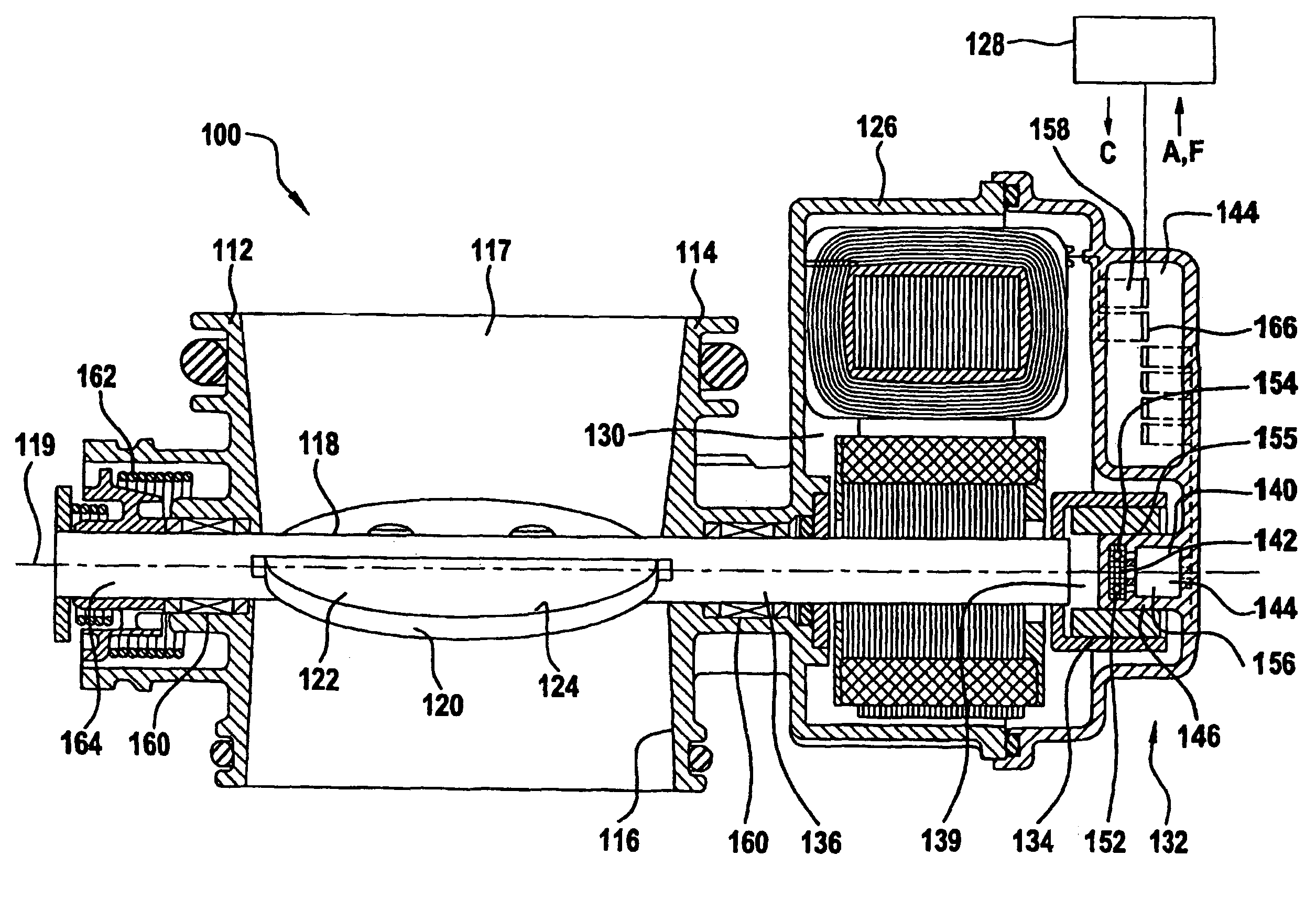
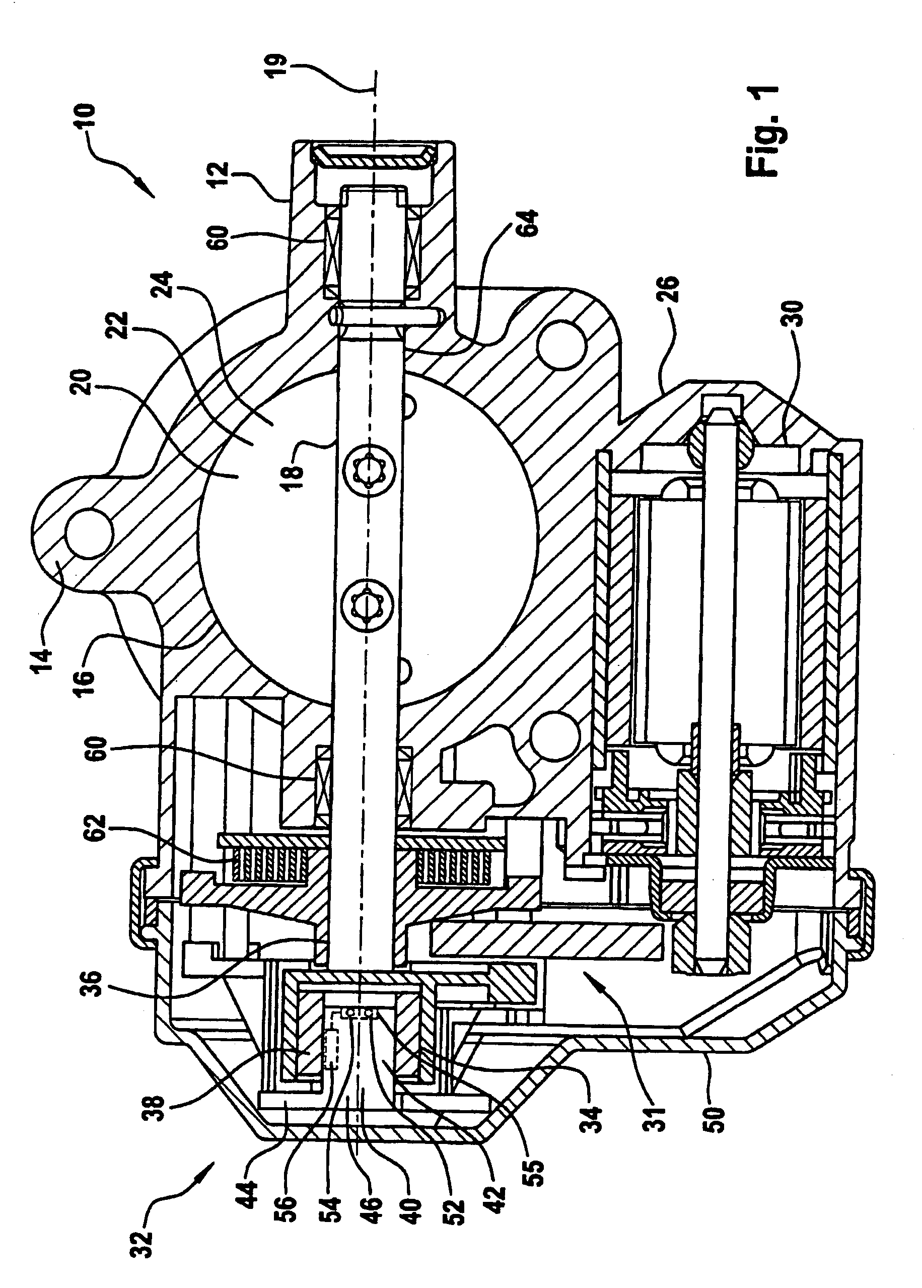
[0033]The butterfly valve connecting piece 10 according to FIG. 1 has the purpose of supplying an air or fuel / air mixture to an actuator (not illustrated), for example an injection device of a motor vehicle (also not illustrated), the quantity of fresh gas which is to be fed to the actuator being capable of being controlled by means of the butterfly valve connecting piece 10. For this purpose, the butterfly valve connecting piece 10 has a housing 12 which is fabricated from metal 14 which is constructed from aluminum in this exemplary embodiment. Alternatively, the housing 12 can however also be manufactured from plastic using an injection molding method. The housing 12 comprises a continuous throttle orifice 16. Air or a fuel / air mixture can be fed to the actuator (not illustrated) via the throttle orifice 16.

[0034]In order to set the volume of fresh gas which is to be fed to the actuator, a b...


PUM


Abstract

The invention relates to a method for the contactless detection of the position of a butterfly-valve shaft of a butterfly valve connecting piece, the butterfly-valve shaft being driven by an electric actuator and having a magnet at one end, which is aligned in a contactless manner with a sensor that is located on a cover. An aim of the invention is to reliably guarantee the detection of the position of the butterfly-valve shaft, even over particularly long periods of time using a contactless position detection device. To achieve this, the sensor has a first and a second magnetoresistive sensor element, an approximately sinusoidal signal being generated in the first sensor element and an approximately cosinusodial signal being generated in the second sensor element by means of the magnet, during the rotation of the butterfly-valve shaft. According to the method, an approximately arc tangential signal is generated in the butterfly-valve connecting signal. The control signal is fed to the actuator that is located in the butterfly-valve connecting piece, to adjust the position of the butterfly-valve shaft.

Description

CROSS REFERENCE TO RELATED APPLICATIONS[0001]The present application is a continuation of international application PCT / DE02 / 02129, filed Jun. 11, 2002, and which designated the United States, and further claims priority to German reference 10133631.4, filed Jul. 11, 2001, the both of which are herein incorporated by reference.BACKGROUND OF THE INVENTION[0002]The invention relates to a method for the contactless detection of the position of a butterfly valve shaft of a butterfly valve connecting piece, the butterfly valve connecting piece having a housing which can be closed off by a lid, and a throttle orifice which is arranged in the housing, for a butterfly valve which is arranged on the butterfly valve shaft, the butterfly valve shaft being capable of being driven by an electric actuator drive and having, at one of its ends, a magnet which is arranged in contactless alignment with a sensor which is arranged on the lid. It also relates to a butterfly valve connecting piece having...

Claims


Application Information

Patent Timeline
Patent Type & Authority Patents(United States)
IPC IPC(8): F16K31/02G01B7/30F02D9/00F02D9/02F02D11/10F02D35/00G01B7/00G01D5/12G01D5/14G01D5/16
CPCF02D11/106G01D5/145F05C2201/021F02D2200/0404Y10T137/8242
Inventor WIESE, PETER
Owner CONTINENTAL AUTOMOTIVE GMBH
Why Eureka
Try Eureka