
Bifurcated stent for percutaneous arterialization of the coronary sinus and retrograde perfusion of the myocardium

Inactive Publication Date: 2006-05-02
MARTIN ERIC C
View PDF26 Cites 55 Cited by
  • Summary
  • Abstract
  • Description
  • Claims
  • Application Information

AI Technical Summary

Benefits of technology

[0008]It is an object of the present invention to provide a novel covered stent for providing retrograde flow of oxygenated blood from the left ventricle to the myocardium via the coronary sinus without a significant or deleterious left-to-right shunt. The present invention includes a main covered stent and a side limb, generally contemplating a Y or a T shaped bifurcated stent.
[0014]Blood from the left ventricle flows through the leading end and into the main covered stent. Because of the graft, blood then flows either out into the right atrium through the trailing end or into the upstream portion of the coronary sinus through the opening and the side stent. Some blood may also flow back into the left ventricle. Thus, the size of the passageway at the leading end controls the amount of blood flowing into the main covered stent; the size of the passageway at the trailing end controls the amount of blood flowing into the right atrium (“left-to-right shunt”); and the size of passageway of the side limb controls the amount of blood flowing into the upstream portion of the coronary sinus. These three sizes are interrelated, and therefore interdependently control the amount of retrograde flow. For example, diminishing the amount of left-to-right shunt increases the pressure in the coronary sinus while directing more blood flow through the side limb. Some amount of blood flow into the right atrium, however, is necessary to prevent excessive pressure build-up in the coronary sinus. Preferably, the sizes of the three passageways work together to prevent the coronary sinus pressure from rising above a suitable level, e.g., of about 50 mm Hg or in the alternative of about half systemic pressure, while at the same time avoiding excessive left-to-right shunting.

Problems solved by technology

Although Nelson requires a pressure sensitive valve that prevents pressure build-up inside the coronary sinus from rising above 60 mm Hg, Nelson does not teach how such a valve may be constructed.
Further, it is unlikely that such a device may be introduced percutaneously and will likely require invasive surgery.
The stent employed by Patel, et al., however, results in a significant shunting of oxygenated blood from the left ventricle to the right atrium (hereinafter “left-to-right shunt”).

Method used


Image

  • Bifurcated stent for percutaneous arterialization of the coronary sinus and retrograde perfusion of the myocardium
  • Bifurcated stent for percutaneous arterialization of the coronary sinus and retrograde perfusion of the myocardium
  • Bifurcated stent for percutaneous arterialization of the coronary sinus and retrograde perfusion of the myocardium

Examples


Embodiment Construction

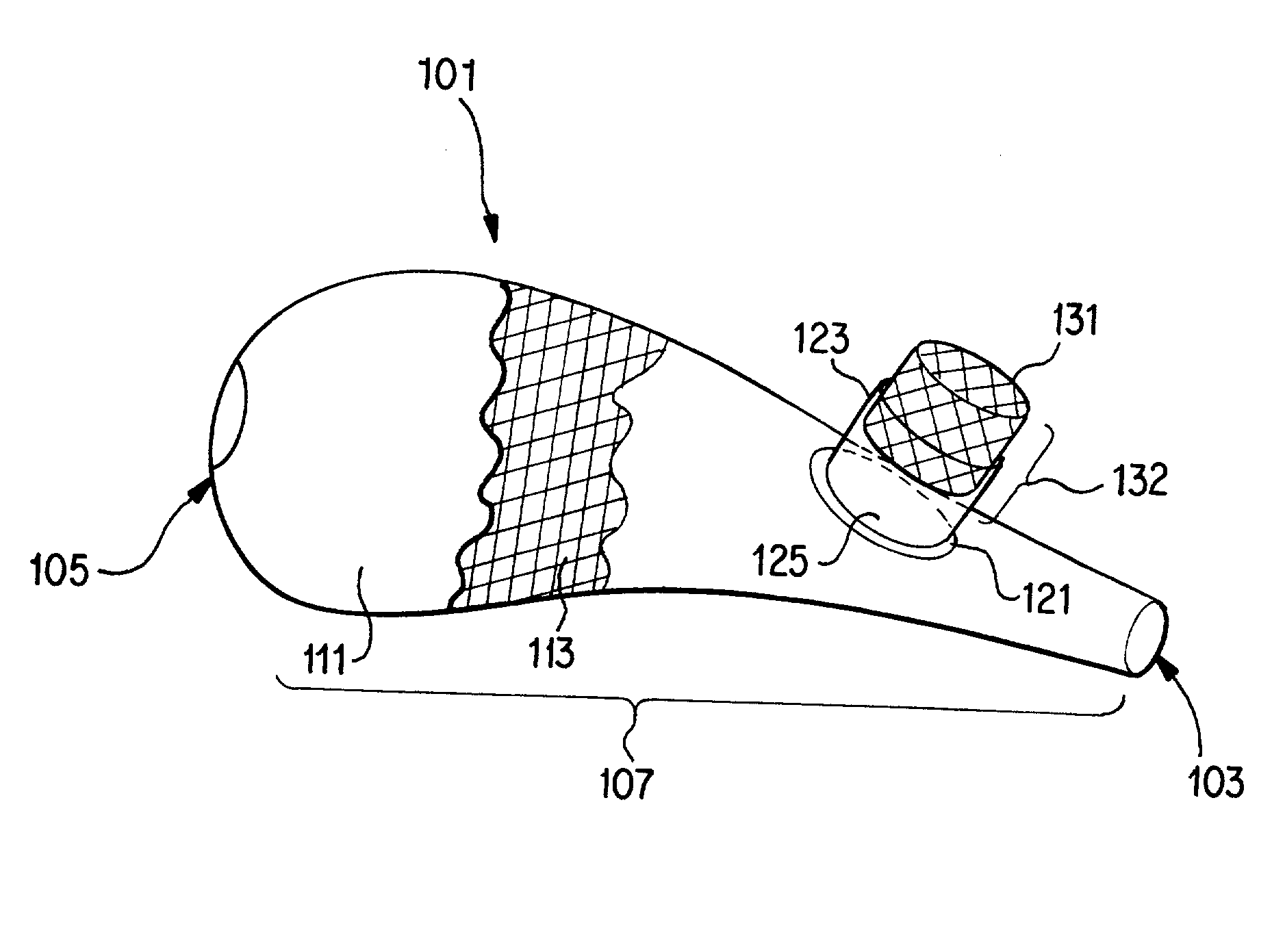
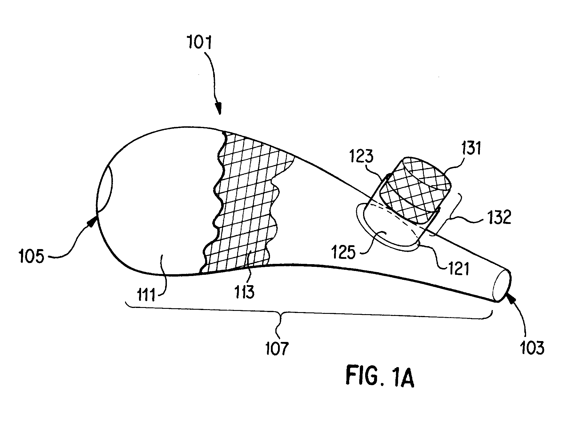
[0022]A preferred embodiment of a bifurcated stent 101 according to the present invention is illustrated in FIG. 1A. The bifurcated stent 101 generally has a main covered stent 107 and a side limb 132. The main covered stent 107 generally has a tubular shape with a passageway therethrough, having a leading end 103 and a trailing end 105. The main covered stent 107 may have a slight bend or may otherwise be straight along its extent.

[0023]The main covered stent 107 generally refers to a combination of an underlying main stent 113 (bare stent) and a graft 111 (covering). The graft 111 is preferably inside the main stent 113, but may also be outside the main stent 113. In another embodiment, the stent 113 may be sandwiched between an outer graft and an inner graft (not pictured). The graft 111 is made from any of a number of commercially available materials such as PET, PTFE, or other suitable material as known in the art. Hereinafter, the combination of the graft 111 and the main sten...


PUM


Abstract

The present invention provides a novel bifurcated stent for providing retrograde flow of oxygenated blood from the left ventricle to the myocardium via the coronary sinus without a significant or deleterious left-to-right shunt. The present invention includes a main covered stent and a side limb, generally contemplating a Y or a T shaped bifurcated stent.

Description

BACKGROUND[0001]I. Field of Invention[0002]The present invention contemplates a bifurcated stent for supplying oxygenated blood retrogradely from the left ventricle to the myocardium through the coronary sinus. The percutaneously-delivered stent directs blood from the left ventricle to the coronary sinus. By controlling the amount of blood flowing into the bifurcated stent and the right atrium, blood is directed retrogradely through the side limb of the present invention to the heart tissue.[0003]II. Description of Related Technology[0004]Retrograde perfusion of the heart through the coronary sinus has long been known for treating end-stage heart disease. Previous methods, among others, have attempted to connect the aorta to the coronary sinus during open-heart surgery using a graft of the jugular vein, the internal mammary artery, or the carotid artery. Alternatively, an occlusion balloon has been used for a short period of time.[0005]Nelson et al. (U.S. Pat. No. 5,824,071, 1998) d...

Claims


Application Information

Patent Timeline
IPC IPC(8): A61F2/06A61F2/00A61F2/02A61F2/07A61F2/90A61F2/95
CPCA61F2/07A61F2/2493A61F2/95A61F2002/065A61F2220/0075A61F2250/0037A61F2250/0039A61F2/90A61F2002/075A61F2002/072
Inventor MARTIN, ERIC C.
Owner MARTIN ERIC C
Features
  • Generate Ideas
  • Intellectual Property
  • Life Sciences
  • Materials
  • Tech Scout
  • Unparalleled Data Quality
  • Higher Quality Content
  • 60% Fewer Hallucinations
Learn More