Capacitive micromachined ultrasound transducer fabricated with epitaxial silicon membrane

a micro-machined, ultrasound transducer technology, applied in the field of electrostatic sensors, can solve the problems of low yield and non-uniformity of diaphragms of fabricated cmuts using surface micromachining techniques, and the use of soi wafers may not be cost effective, and the process flexibility is limited

Inactive Publication Date: 2006-05-02
GENERAL ELECTRIC CO
View PDF21 Cites 87 Cited by
  • Summary
  • Abstract
  • Description
  • Claims
  • Application Information

AI Technical Summary

Benefits of technology

[0006]Briefly in accordance with one embodiment of the present technique, a capacitive micromachined ultrasound transducer (cMUT) cell is presented. The cMUT cell includes a lower electrode. Furthermore, the cMUT cell includes a diaphragm disposed adjacent to the lower electrode such that a gap having a first gap width is formed between the diaphragm and the lower electrode, wherein the diaphragm comprises one of a first epitaxial layer or a first polysilicon layer. In addition, a stress reducing material is disposed in one of the first epitaxial layer or the first polysilicon layer.
[0007]In accordance with as...

Problems solved by technology

However, as will be appreciated, cMUTs fabricated employing surface micromachining techniques suffer from low yield and non-uniformities in the diaphragm.
However, use of the SOI wafers may not be cost ...

Method used


Image

  • Capacitive micromachined ultrasound transducer fabricated with epitaxial silicon membrane
  • Capacitive micromachined ultrasound transducer fabricated with epitaxial silicon membrane
  • Capacitive micromachined ultrasound transducer fabricated with epitaxial silicon membrane

Examples


embodiment 24

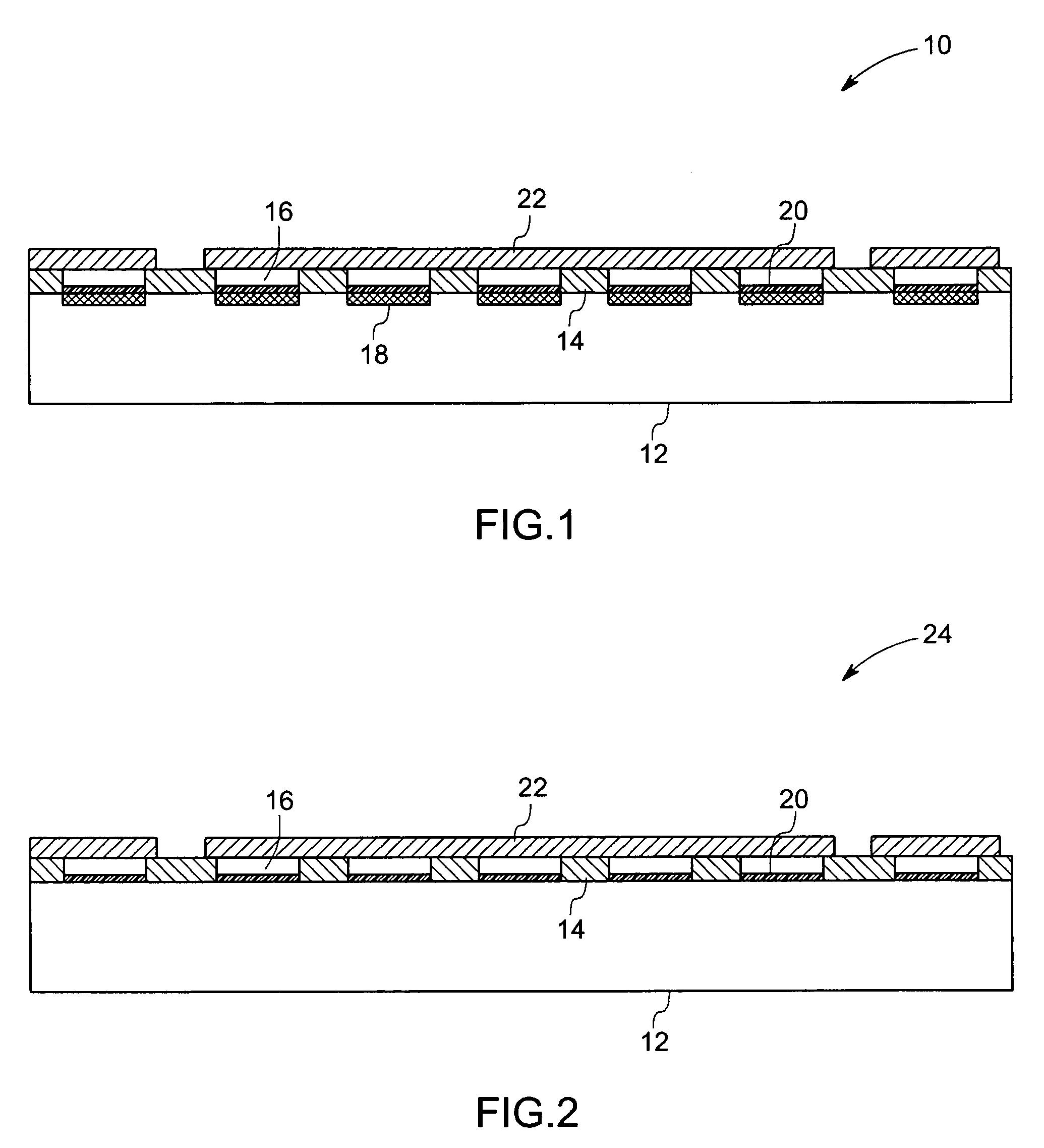
[0026]Referring now to FIG. 2, a side view of a cross-section of an alternate embodiment 24 of the cMUT cell 10 of FIG. 1 is illustrated. In accordance with aspects of the present technique, the substrate 12 may be highly doped. Consequently, the substrate 12 may be configured to exhibit low resistivity. In the illustrated embodiment of FIG. 2, the substrate 12 may be configured for use as the lower electrode. The diaphragm 22 may include an epitaxial layer of silicon. Further, in accordance with aspects of the present technique, the epitaxial layer of silicon may include a stress reducing material, such as, but not limited to, germanium, disposed therethrough. As previously mentioned, the diaphragm may include p-type or n-type material and may be configured to exhibit low resistivity.

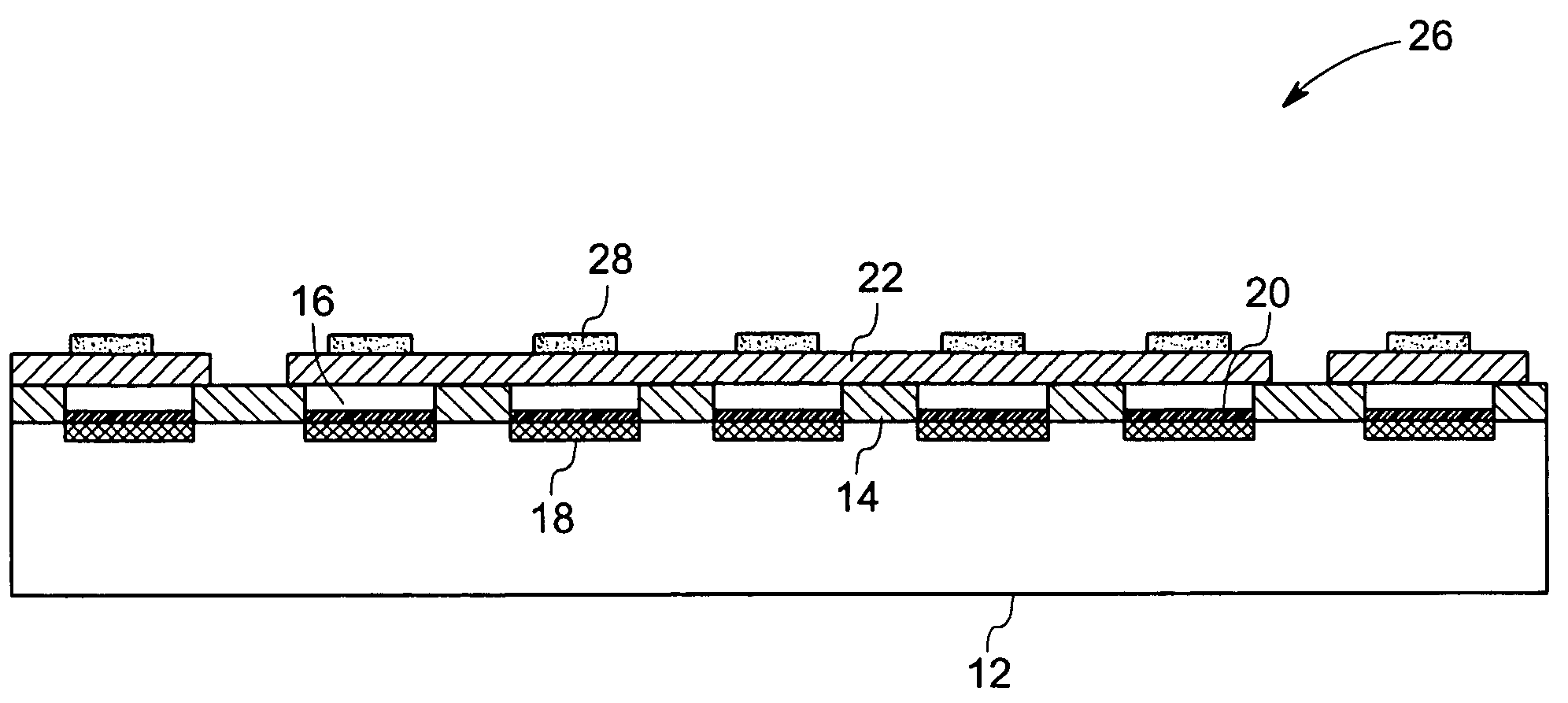
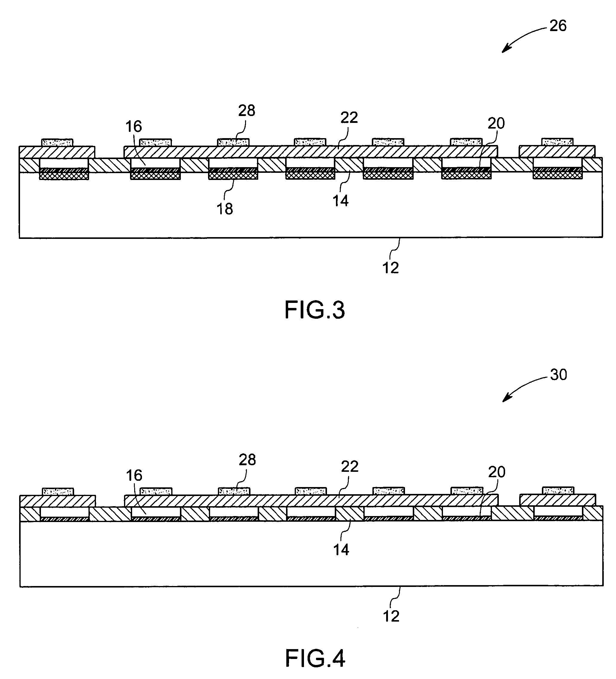
[0027]Turning out to FIG. 3, a side view of a cross-section of another exemplary embodiment 26 of a cMUT cell is illustrated. In this embodiment an upper electrode 28 may be patterned on the diaphragm ...

embodiment 30

[0029]FIG. 4 illustrates a side view of a cross-section of an alternate embodiment 30 of the cMUT cell 26 illustrated in FIG. 3. In the illustrated embodiment, the substrate 12 is configured for use as the lower electrode. The substrate 12 may be of p-type or n-type material. Further the substrate 12 may be highly doped and thus may be configured to exhibit low resistivity.

exemplary embodiment 32

[0030]FIG. 5 illustrates a side view of a cross-section of an exemplary embodiment 32 of a cMUT cell. In this embodiment, a material that may be configured for use as an upper electrode 28 may be implanted in the diaphragm 22. Alternatively, the upper electrode 28 may be formed by diffusing the material in the diaphragm 22. In this embodiment, the upper electrode 28 may include p-type or n-type material. Additionally, the implanted or diffused upper electrode 28 may be highly doped and thereby be configured to exhibit low resistivity. As previously mentioned, the diaphragm 22 may be of p-type or n-type material and may be configured to exhibit high resistivity.

[0031]Additionally, the substrate 12 may include a p-type or an n-type silicon wafer. In addition, a level of doping in the substrate 12 may be low, and thereby may result in the substrate 12 exhibiting high resistivity. Furthermore, the lower electrode 18 may be implanted or diffused in the substrate 12. In this embodiment, t...


PUM


Abstract

A capacitive micromachined ultrasound transducer (cMUT) cell is presented. The cMUT cell includes a lower electrode. Furthermore, the cMUT cell includes a diaphragm disposed adjacent to the lower electrode such that a gap having a first gap width is formed between the diaphragm and the lower electrode, wherein the diaphragm comprises one of a first epitaxial layer or a first polysilicon layer. In addition, a stress reducing material is disposed in the first epitaxial layer.

Description

BACKGROUND[0001]The invention relates generally to electrostatic sensors, and more specifically to capacitive micromachined ultrasound transducers (cMUTs).[0002]Transducers are devices that transform input signals of one form into output signals of a different form. Commonly used transducers include, heat sensors, pressure sensors, light sensors, and acoustic sensors. An example of an acoustic sensor is an ultrasonic transducer, which may be implemented in medical imaging, non-destructive evaluation, and other applications.[0003]One form of an ultrasonic transducer is a capacitive micromachined ultrasound transducer (cMUT). A cMUT cell generally includes a substrate that contains a lower electrode, a diaphragm suspended over the substrate by means of support posts, and a metallization layer that serves as an upper electrode. The lower electrode, diaphragm, and the upper electrode define a cavity. As will be appreciated by one skilled in the art, the support posts typically engage th...

Claims


Application Information

Patent Timeline
IPC IPC(8): H01L21/00
CPCB06B1/0292
Inventor SMITH, LOWELL SCOTTMILLS, DAVID MARTINFORTIN, JEFFREY BERNARDTIAN, WEI-CHENGLOGAN, JOHN ROBERT
Owner GENERAL ELECTRIC CO
Why Eureka
Try Eureka