Image heating apparatus of electromagnetic induction heating type
a heating apparatus and electromagnetic induction technology, applied in the field of image heating apparatus, can solve the problems of difficult removal of coil from jig, inability to insert coil b>2/b> into the fixing roller, and coil damage, etc., and achieve the effect of convenient assembly
- Summary
- Abstract
- Description
- Claims
- Application Information
AI Technical Summary
Benefits of technology
Problems solved by technology
Method used
Image
Examples
first embodiment
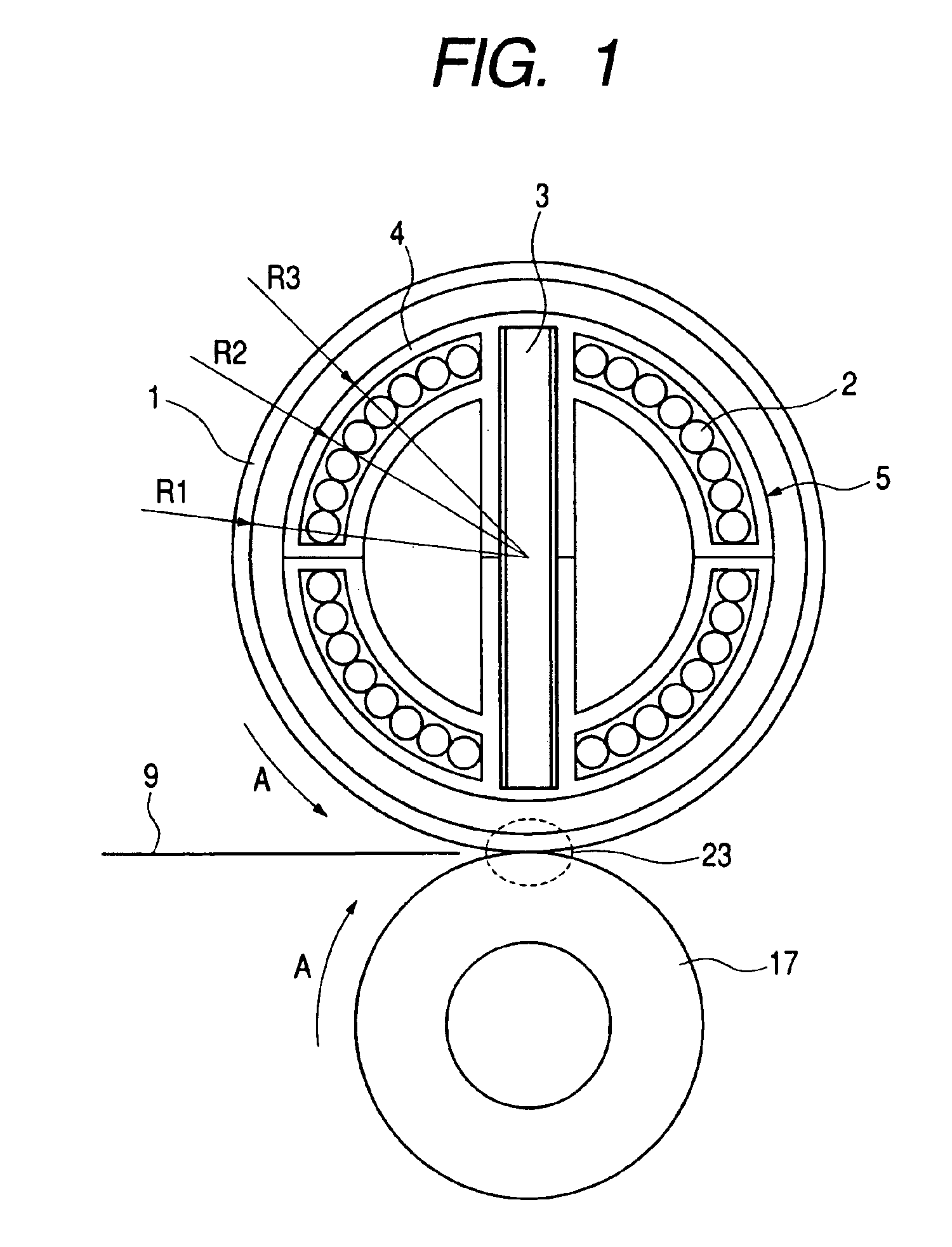
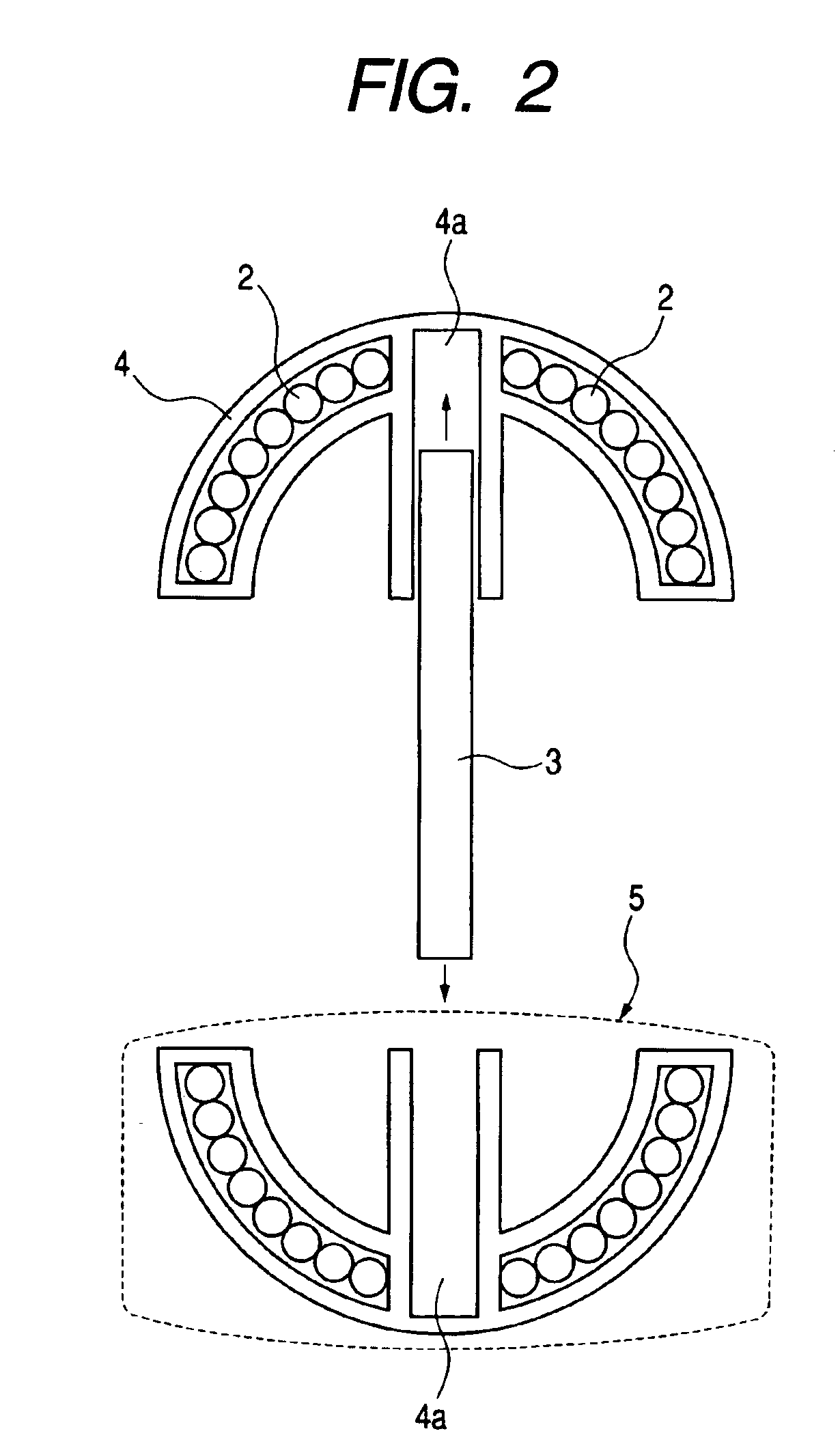
[0033]A description is given with reference to FIGS. 1 and 2 on a heating apparatus and its two coil units according to this embodiment. In FIG. 1, a heating roller 1 is a cylindrical electroconductive member (heating member) and is supported in a manner that allows the heating roller 1 to rotate about the central axis of the cylinder. The electroconductive member constituting the heating roller 1 is an iron, nickel, stainless steel, or other member that has magnetic characteristics.
[0034]Inside the heating roller 1, two semi-cylindrical coil units (a first coil unit and a second coil unit) 5 are joined together to form an approximately cylindrical (or columnar) shape since the cross-section of each of the first coil unit and the second coil unit is arced, and the resultant cylinder is centered on the rotation axis of the heating roller 1. The combined coil units are fixed to a side plate (not shown) of the heating apparatus and thus prevented from rotating. The resultant coil is a ...
second embodiment
[0063]FIG. 4 is a schematic sectional view of a heating apparatus according to a second embodiment.
[0064]In this embodiment, two coil core units (coil units) 6 are joined to each other, and each coil core unit is composed of a coil 2 for generating a magnetic field, a core 3 composed of a magnetic body, and a holder 4 made of phenol resin. The coil 2, the core 3, and the holder 4 are unitarily formed. For the rest, the heating apparatus of this embodiment and the heating apparatus of the first embodiment are structured similarly.
[0065]That is, the core 3 is added to the coil 2 and the holder 4 in integral molding to constitute the coil core unit 6 in this embodiment. This embodiment is thus improved in ease of assembling work as well as in work efficiency since the step of inserting the core 3 is eliminated.
[0066]This embodiment also has an effect of reducing problems brought around by the core rattling, such as chipping and a change in characteristic. The coil core units 6 are fixe...
third embodiment
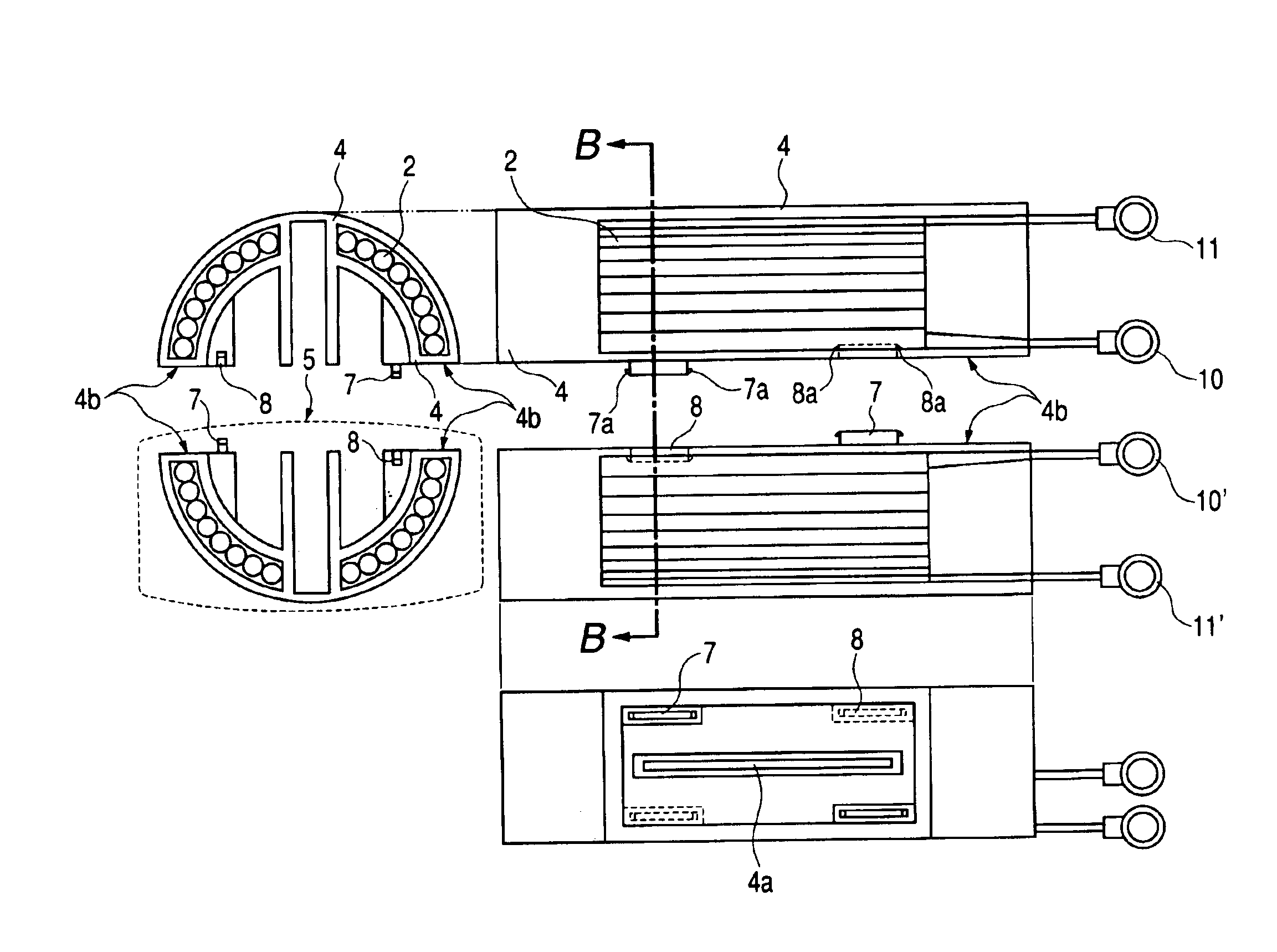
[0069]FIG. 5 is a schematic sectional view of two coil units 5 of a third embodiment taken along a line B—B, a side view of the two coil units, and a plan view of one of the coil units.
[0070]In the third embodiment shown in FIG. 5, each coil unit 5 has an approximately semi-cylindrical shape and includes a holder 4. The coil units 5 are joined to each other at surfaces 4b of each holder 4. Two convex holding portions 7 are arranged diagonally from each other and two concave holding portions 8 are arranged diagonally from each other in the vicinity of four corners of the surface 4b. The convex holding portions and the concave holding portions are referred to as junction portions.
[0071]Each convex holding portion 7 is an approximately rectangular column that protrudes vertically from the associated surface 4b. A claw 7a is provided in each side face in the coil unit cylinder axis direction of the rectangular column. Each convex holding portion 7 is inserted into the associated concave...
PUM
 Abstract
Description
Claims
Application Information
 - R&D
- Intellectual Property
- Life Sciences
- Materials
- Tech Scout
- Unparalleled Data Quality
- Higher Quality Content
- 60% Fewer Hallucinations
Browse by: Latest US Patents, China's latest patents, Technical Efficacy Thesaurus, Application Domain, Technology Topic, Popular Technical Reports.
© 2025 PatSnap. All rights reserved.Legal|Privacy policy|Modern Slavery Act Transparency Statement|Sitemap|About US| Contact US: help@patsnap.com


