Vertical vibrator

a vertical and vibrating technology, applied in the direction of repeater circuits, mechanical vibration separation, magnetic circuit shape/form/construction, etc., can solve the problems of limited miniaturization and simplification of the conventional actuator b>2/b>, and reducing the life span of the motor. , to achieve the effect of stable vibration wave form

Active Publication Date: 2006-05-02
MPLUS
View PDF7 Cites 57 Cited by
  • Summary
  • Abstract
  • Description
  • Claims
  • Application Information

AI Technical Summary

Benefits of technology

[0027]The present invention has been made to solve the above problems, and it is an object of the present invention to provide a vertical vibrator, designed to absorb contact noise and impact which can occur upon excessive vertical displacement of a vibration part, thereby providing a stable vibration wave form.
[0028]It is another object of the present invention to provide a vertical vibrator designed to ensure convenient and appropriate positioning of magnetic fluids by use of magnetic flux leaked from a yoke, and designed to have an extended life span by increasing coupling force between a magnet and the yoke.

Problems solved by technology

However, when driving the motor having such a structure, the brushes 25 pass through a minute gap between segments of the commutator 15, generating mechanical friction, electrical sparks and abrasion therein, whereby foreign substances, such as black powders, are produced, and reduce the life span of the motor.
However, the conventional actuator 2 described above has a number of limitations due to the number of components and complicated construction thereof.
Namely, miniaturization and simplification of the conventional actuator 2 are limited and manufacture thereof is costly.
This contact noise is the main source of noise associated with operation of the vertical vibrator.

Method used


Image

  • Vertical vibrator
  • Vertical vibrator
  • Vertical vibrator

Examples


first embodiment

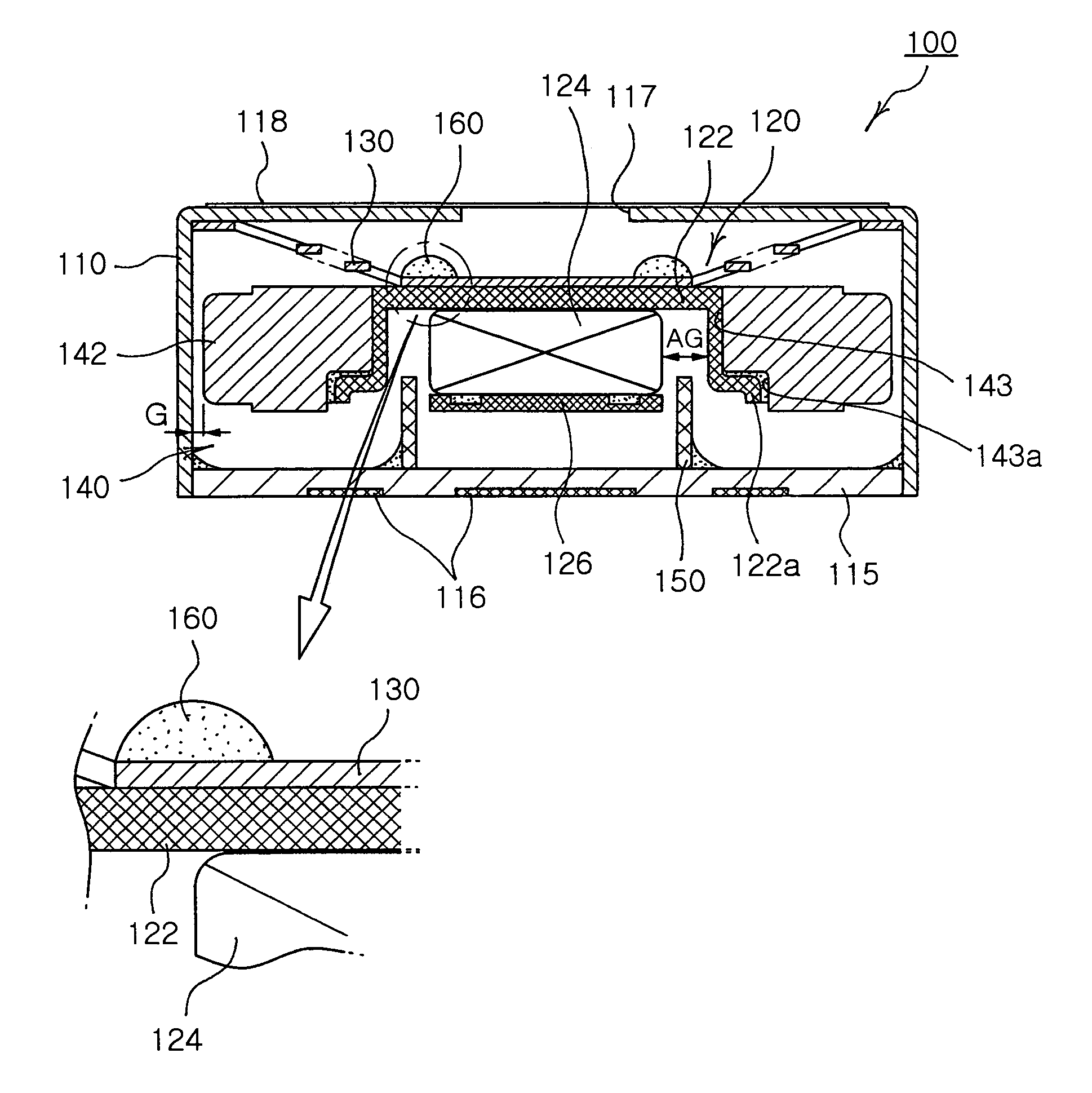
[0065]FIG. 4 is a cross-sectional view of a vertical vibrator according to the present invention. As shown in FIG. 4, the vertical vibrator 100 of the invention can prevent contact noise from being generated by undesired contact between an upper structure and a vibration member vertically vibrating with regard to a fixed member, and allows convenient and accurate positioning of a direct contact-preventing member by use of a leaked magnetic flux, thereby increasing vibration efficiency while ensuring stable vertical vibration.

[0066]The vertical vibrator 100 comprises a casing 110, a magnetic field part 120, a spring member 130, a vibration part 140, a vibration coil 150, and a magnetic fluid 160.

[0067]The casing 110 serves as a receiving member having a space of a predetermined size defined therein, and is closed at a lower portion thereof by a bracket 115.

[0068]The casing 110 has at least one injection hole 117 of a predetermined size perforated through the casing 110. Preferably, t...

fourth embodiment

[0114]Moreover, as with the fourth embodiment, the yoke 122 may be provided on the upper surface thereof with the ring-shaped positioning member 162 which is magnetized by the magnetic force of the magnet 124.

[0115]When power is applied to the vibration coil 150 of the vertical vibrator 100, 100a, 100b, 100c or 100d constructed as described above, the vibration part 140 comprising the weight 142 integrally mounted on the yoke 122 and the magnetic field part 120 vertically vibrates by virtue of linkage between the electric field generated from the coil 150 and the magnetic field generated from the magnetic field part 120 constituted by the magnet 124, provided as the permanent magnet, and the lower plate 126 provided to the lower portion of the yoke 122 comprising the magnet 124. At this time, the vertical amplitude of the vibration part 140 is determined by the resilient force of the spring member 130 or 130a connected at the upper end to the casing 100.

[0116]During the vertical vib...


PUM


Abstract

A vertical vibrator is disclosed. The vibrator comprises a casing, a magnetic field part including a yoke and a magnet fixed to an inner surface of the yoke, a spring member fixed at one end to the casing and at the other end to the magnetic field part, a vibration part having a weight integrally mounted to the magnetic field part and vibrating together with the magnetic field part through the spring member, a vibration coil located below the magnetic field part for generating an electric field, and a magnetic fluid applied to an upper surface of the spring member corresponding to the magnet and fixed in position by a magnetic flux. The vibrator absorbs contact noise and impact caused by contact between the vibration part and the other members while ensuring convenient and appropriate positioning of the magnetic fluid, thereby having an extended life span.

Description

RELATED APPLICATION[0001]The present invention is based on, and claims priority from, Korean Patent Application Number 2004-47255, filed Jun. 23, 2004 and Korean Patent Application No. 2005-46622 filed Jun. 1, 2005, the disclosure of which is incorporated by reference herein in its entirety.BACKGROUND OF THE INVENTION[0002]1. Field of the Invention[0003]The present invention generally relates to a vertical vibrator, and, more particularly, to a vertical vibrator, designed to achieve a stable vibration waveform by absorbing contact noise and impact caused by contact between a vibration part and an upper structure upon excessive upward vibration of the vibration part, to ensure convenient and appropriate positioning of magnetic fluid by use of the magnetic flux leaked from a yoke, and to have an extended life span by increasing coupling force between a magnet and the yoke.[0004]2. Description of the Related Art[0005]Communication instruments generally employ ring tones and vibration i...

Claims


Application Information

Patent Timeline
Patent Type & Authority Patents(United States)
IPC IPC(8): H02K1/06H02K1/34H02K33/02H02K5/10B06B1/04G10KH02K7/06H02K33/16H02K41/00
CPCH02K33/16B06B1/045H02K7/065
Inventor CHOI, JOONPARK, IL OUNG
Owner MPLUS
Why Eureka
Try Eureka