
Field assembly for a motor and method of making same

a field assembly and motor technology, applied in the direction of manufacturing stator/rotor body, magnetic circuit rotating parts, magnetic circuit shape/form/construction, etc., can solve the problems of requiring injection molding of magnetic materials, affecting the quality of motor components, and the most expensive type of magnetic materials per unit flux, etc., to achieve the effect of facilitating rolling, reducing air gaps, and facilitating rolling

Inactive Publication Date: 2006-05-02
BLACK & DECKER INC
View PDF158 Cites 48 Cited by
  • Summary
  • Abstract
  • Description
  • Claims
  • Application Information

AI Technical Summary

Benefits of technology

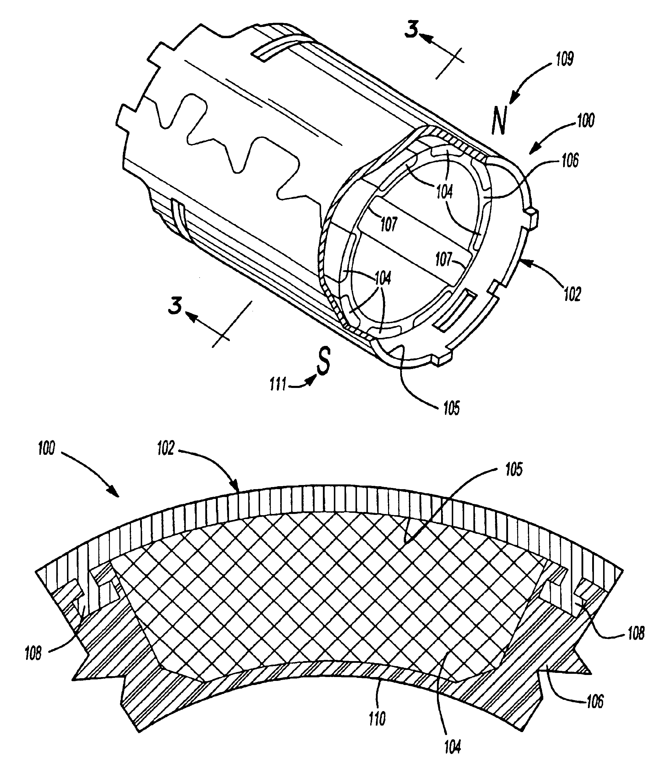
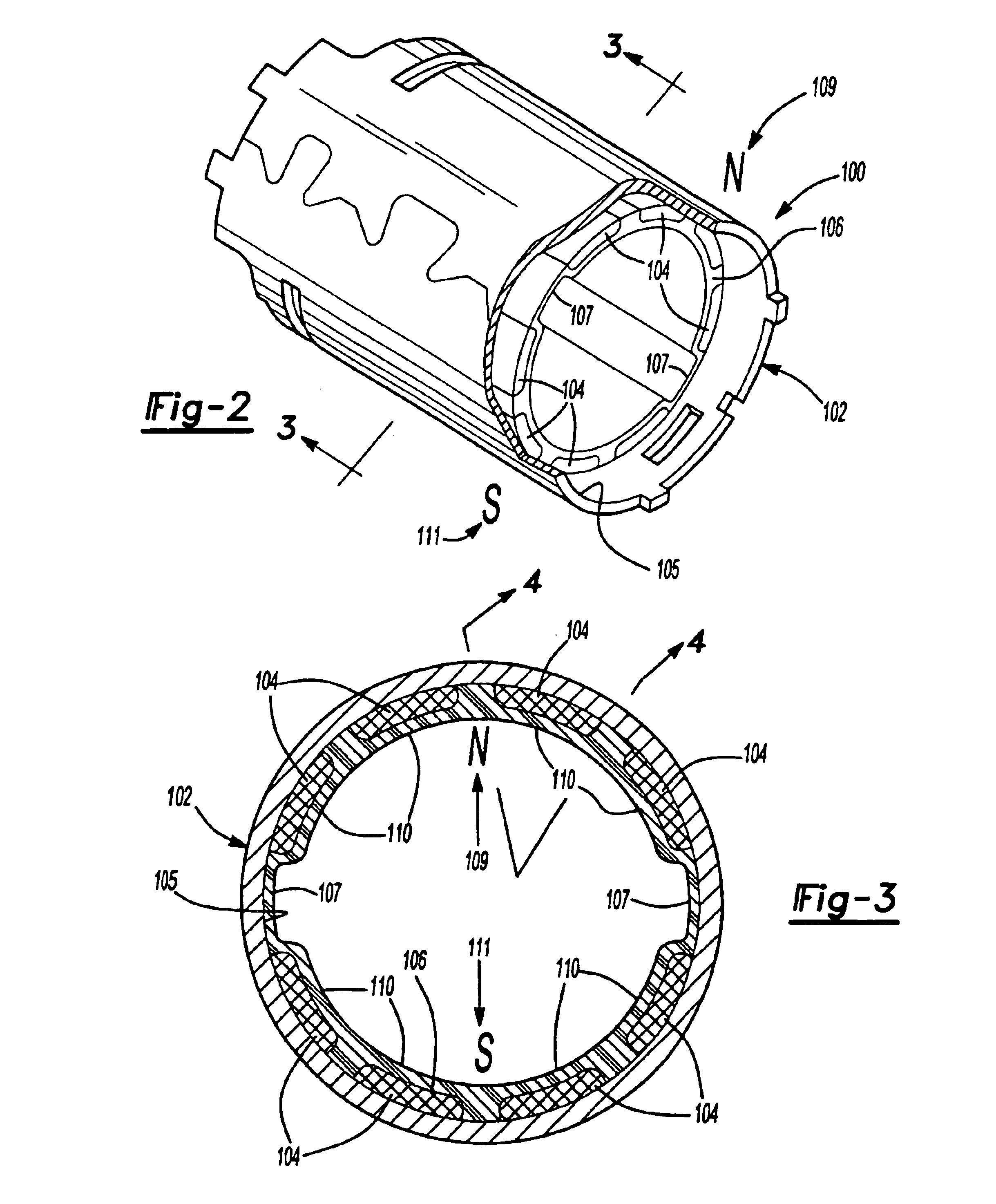
[0010]In accordance with another aspect of the invention, the anchors extend radially inwardly and have a height greater than a height of the magnets so that a straight line distance between inward ends of adjacent anchors having a magnet therebetween is less than a straight line distance between opposed side edges of an inner surface of the magnet. The adjacent anchors thus prevent the magnet between them from moving radially inwardly during the molding of the plastic.
[0012]In accordance with another aspect of the invention, each anchor adjacent a magnet has first and second base portions adjacent opposite ends of the magnet to which the anchor is adjacent. The anchor also has a generally rectangular segment, spaced away from the inner surface of the cylinder, extending between the first and second base portions. The anchor is appropriately dimensioned as a flux spreader. In an aspect of the invention, each anchor has at least one lengthwise split to facilitate rolling the stamped blank from which the cylinder is rolled. In an aspect of the invention, holes are provided where the base portions of the anchors meet the inner surface of the cylinder which act as magnetic chokes and also facilitate rolling the cylinder from the stamped blank.
[0013]In accordance with another aspect of the invention, the magnets have stepped edges and each anchor adjacent a side of a magnet includes an inwardly extending finger having a distal end that is received in the stepped edge of the adjacent magnet. The plastic is molded so that there is no layer of plastic molded on the inner surfaces of the magnets to reduce the air gap between the inner surfaces of the magnets and the rotor of the motor armature.
[0015]In accordance with another aspect of the invention, a cylinder / magnet assembly for a stator of a motor is formed by inserting magnets having stepped edges in a cylinder, such as a flux ring or stator housing, placing the cylinder / magnet assembly into an injection molding die and injection molding plastic around the magnets and their stepped edges to secure the magnets in place in the cylinder. In an aspect of the invention, plastic is molded so that it is not disposed on inner surfaces of the magnet to reduce an air gap between the inner surfaces of th magnets and the armature rotor.

Problems solved by technology

As the adhesives age, it is possible that if the device using the electric machine, such as a power tool having a motor, is dropped, that the sudden shock will destroy the bond between the magnet and the housing or flux ring, enabling the magnet to travel within the motor.
The magnet itself could also break.
However, a disadvantage of the anchoring systems described in the above two referenced patent applications is that they require the use of injection molded magnetic material, which is typically the most expensive type of magnetic material per unit flux.

Method used


Image

  • Field assembly for a motor and method of making same
  • Field assembly for a motor and method of making same
  • Field assembly for a motor and method of making same

Examples


Embodiment Construction

[0071]The following description of the preferred embodiment(s) is merely exemplary in nature and is in no way intended to limit the invention, its application, or uses.

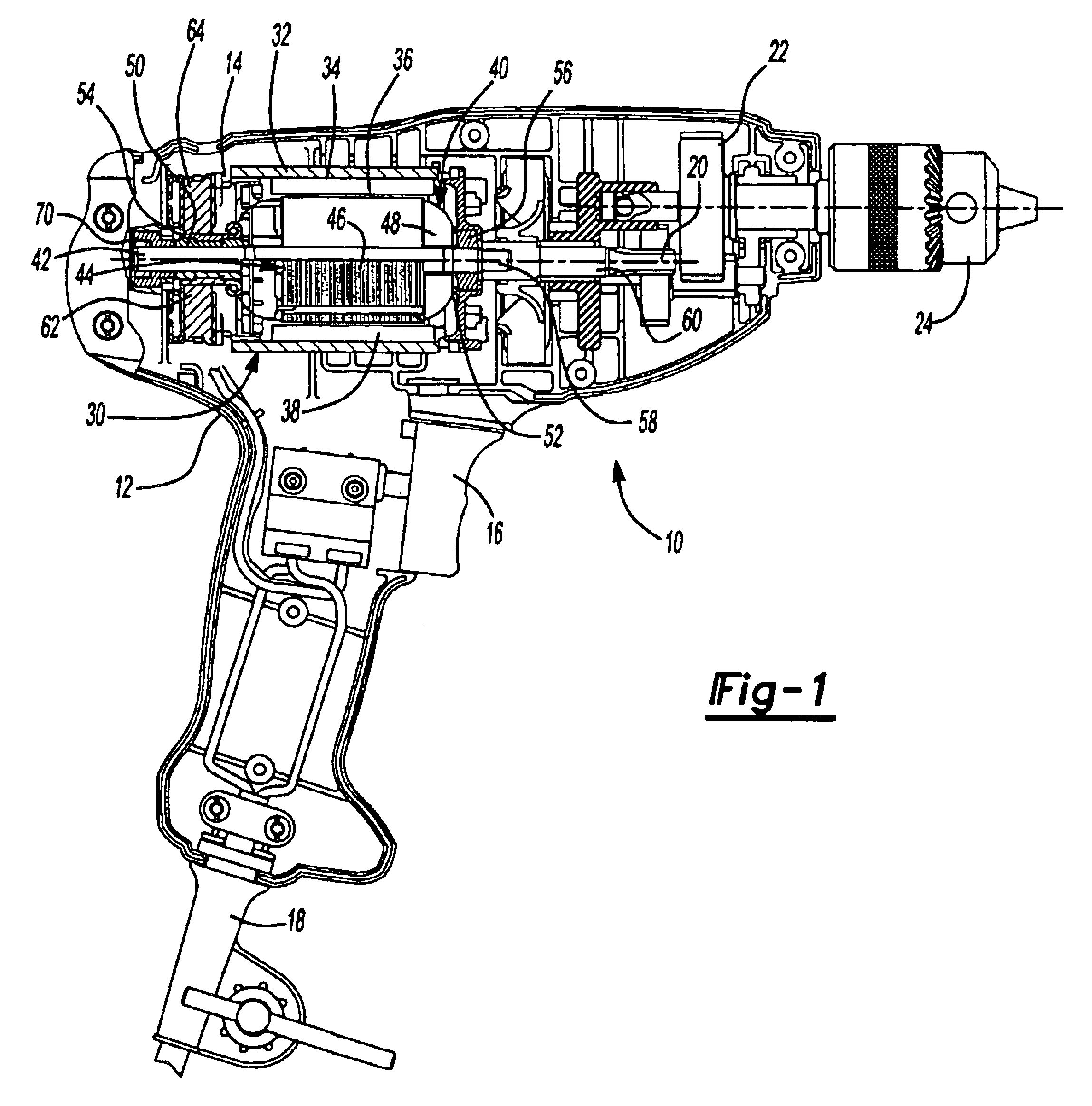
[0072]Turning to FIG. 1, a power tool in accordance with the present invention is illustrated and designated with the reference numeral 10. The power tool 10 is illustrated as a drill; however, any type of power tool may be used with the motor of the present invention. The power tool 10 includes a housing 12 which surrounds a motor 14. An activation member 16 is coupled with the motor 14 as well as with a power source 18. The power source 18 may be a power cord (AC current) or the power tool may have a battery (DC current) (not shown). The motor 14 is coupled with an output 20 which may include a transmission 22 and a chuck 24 to retain a tool (not shown) with the drill.

[0073]The motor 14 includes a stator assembly 30 which includes a housing 32, flux ring 34, and magnets 36 and 38. An armature 40 includes a shaft 42,...


PUM


Abstract

A cylindrical magnet ring assembly having a cylinder magnet flux ring (102) formed with a plurality of inwardly projecting anchors (108); a plurality of permanent magnets (104), wherein the magnet can be formed with step portions (112) in the inner radial surface; a molded plastic member (106) being molded around the magnets and anchors to secure the magnets to a surface of the cylinder flux ring. There are several variations of the embodiments of the invention. Few embodiments are the following: in one aspect of the invention, magnets are inserted into magnet molded around an assembly ring (806) and the molded plastic secures the assembly ring to the flux ring; in another aspect, there are two assembly rings, a first assembly ring (is inserted into the one side of the cylinder flux ring then the second assembly ring is inserted into the other side of the cylinder flux ring and mated to the first assembly ring, after that the molded plastic secures the two assembly rings. The foregoing cylindrical magnet ring assembly is used in a stator of a motor which is used in a power tool.

Description

FIELD OF THE INVENTION[0001]The present invention relates to field assemblies for electric machines.BACKGROUND OF THE INVENTION[0002]In construction of field assemblies for electric machines, magnets must be retained on a cylinder of the field assembly. For example, in a brush type of motor, magnets must typically be retained on a stator housing or a separate flux ring within the stator housing. Ordinarily, these magnets have been glued or adhered to the metallic flux ring or stator housing. This typically involves gluing or adhering each individual magnet to the flux ring or stator housing.[0003]In adhering the magnets to the metallic surface so that the magnets do not shift during use, various types of adhesives have been used. While some of the adhesives have been satisfactory, some adhesives work better than others. As the adhesives age, it is possible that if the device using the electric machine, such as a power tool having a motor, is dropped, that the sudden shock will destr...

Claims


Application Information

Patent Timeline
Patent Type & Authority Patents(United States)
IPC IPC(8): H02K1/17H02K1/27H02K5/00H02K5/08H02K5/173H02K7/14H02K9/06H02K23/04
CPCH02K1/17H02K1/2786H02K5/00H02K5/08H02K5/1735H02K23/04Y10T29/49009H02K9/06Y10T29/49012Y10T29/49011H02K7/145H02K1/2791
Inventor AGNES, MICHAELBOYCE, ALLYNDU, HUNGORTT, EARLVERBRUGGE, BRANDONWALTER, RICHARD T.WANG, REN H.ZHANG, JIAQI
Owner BLACK & DECKER INC
Learn More