Object detection system for vehicle

Active Publication Date: 2006-05-02
MAGNA ELECTRONICS
View PDF46 Cites 1135 Cited by
  • Summary
  • Abstract
  • Description
  • Claims
  • Application Information

AI Technical Summary

Benefits of technology

[0008]The present invention is intended to provide an object detection system, such as a blind spot detection system, a lane change assist or aid system or device, a lane departure warning system, a side object detection system, a reverse park aid system, a forward park aid system, a forward, sideward or rearward collision avoidance system, an adaptive cruise control system, a passive steering system or the like, which is operable to detect and/or identify a vehicle or other object of interest at the side, front or rear of the vehicle equipped with the object detection system. The object detection system of the present invention, such as a lane change assist system, utilizes an edge detection algorithm to detect edges of objects in the captured images and determines if a vehicle is present in a lane adjacent to the equipped or subject vehicle in response to various characteristics of the detected edges, such as the size, location,

Problems solved by technology

Because such systems typically use statistical methodologies to determine a likelihood or probability that a detected object is a vehicle, and for other reasons, the systems may generate false positive detections, where the system indicates that a vehicle is adjacent to, forward of or rearward of the subject vehicle when there is no vehicle adjacent to, forward of or rearward of the subject vehicle, or false negative detections, where the system, for example, indicates that there is no vehicle adjacent to the subject vehicle when there actually is a vehicle in the adjacent lane.
Such frame by frame flow algorithms and systems may not be able to track a vehicle which is moving at generally the same speed as the equipped vehicle, because there may be little or no relative movement between the vehicles and,

Method used


Image

  • Object detection system for vehicle
  • Object detection system for vehicle
  • Object detection system for vehicle

Examples


Example

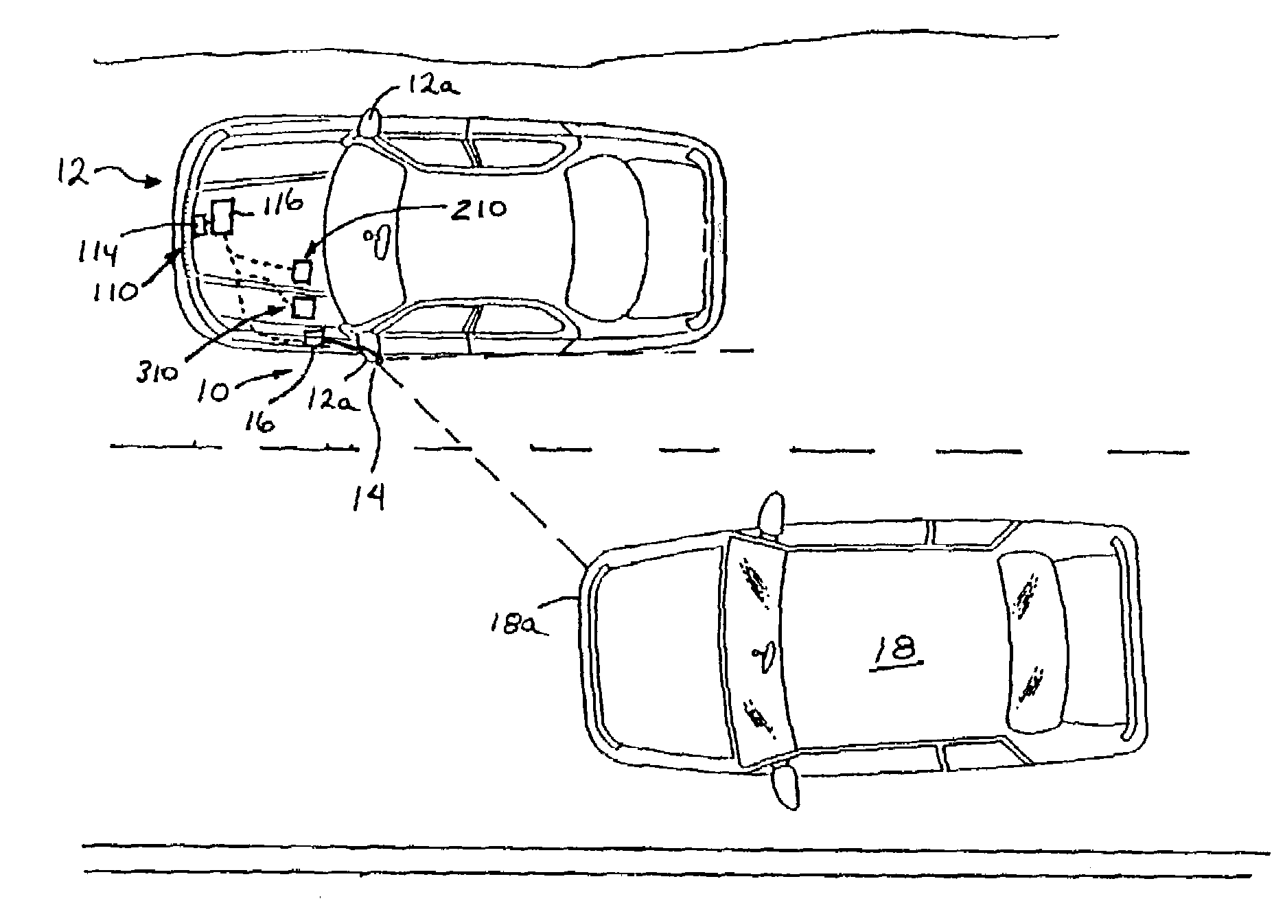
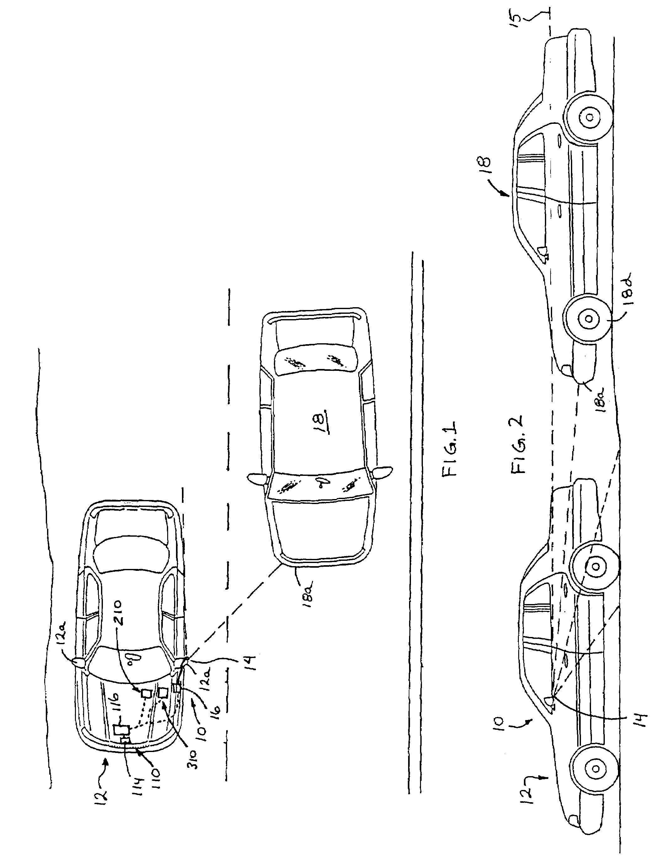
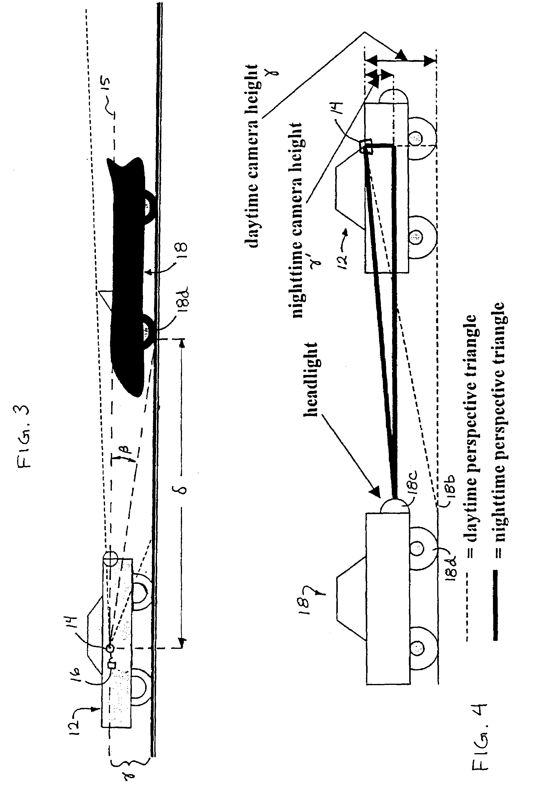
[0043]Referring now to the drawings and the illustrative embodiments depicted therein, an object detection system or imaging system, such as a lane change assist or aid system 10, is positioned at a vehicle 12 and is operable to capture an image of a scene occurring sidewardly and rearwardly at or along one or both sides of vehicle 12 (FIGS. 1–4 and 6). Lane change assist system 10 comprises an image capture device or sensor or camera 14 and a control 16 (FIGS. 3, 9 and 10). Camera 14 captures an image of the scene occurring toward a respective side of the vehicle 12, and control 16 processes the captured image to determine whether another vehicle 18 is present at the side of vehicle 12, as discussed below. Control 16 may be further operable to activate a warning indicator or display or signal device 17 (FIG. 10) to alert the driver of vehicle 12 that another vehicle is present at the side of vehicle 12. The warning or alert signal may be provided to the driver of vehicle 12 in resp...


PUM


Abstract

An imaging system for a vehicle includes an imaging sensor and a control. The imaging sensor is operable to capture an image of a scene occurring exteriorly of the vehicle. The control receives the captured image, which comprises an image data set representative of the exterior scene. The control may apply an edge detection algorithm to a reduced image data set of the image data set. The reduced image data set is representative of a target zone of the captured image. The control may be operable to process the reduced image data set more than other image data, which are representative of areas of the captured image outside of the target zone, to detect objects present within the target zone. The imaging system may be associated with a side object detection system, a lane change assist system, a lane departure warning system and/or the like.

Description

CROSS REFERENCE TO RELATED APPLICATIONS[0001]The present application claims priority of U.S. provisional applications, Ser. No. 60 / 433,700, filed Dec. 16, 2002 by Pawlicki et al. for VEHICLE OBJECT DETECTION SYSTEM; and Ser. No. 60 / 377,524, filed May 3, 2002 by McMahon for LANE DEPARTURE WARNING SYSTEM, which are hereby incorporated herein by reference in their entireties.FIELD OF THE INVENTION[0002]The present invention relates generally to vision or imaging systems for vehicles and is related to object detection systems and, more particularly, to imaging systems which are operable to determine if a vehicle or object of interest is adjacent to, forward of or rearward of the subject vehicle to assist the driver in changing lanes or parking the vehicle. The present invention also relates generally to a lane departure warning system for a vehicle.BACKGROUND OF THE INVENTION[0003]Many lane change aid / side object detection / lane departure warning devices or systems and the like have been...

Claims


Application Information

Patent Timeline
IPC IPC(8): B60Q1/00B60K31/00B60Q1/52G01S11/12G01S13/931G06K9/00
CPCG06K9/00825B60Q1/525B60Q9/008B60T7/22G01S11/12G06K9/00791G06K9/00798G06T7/0042G08G1/16B60K31/0008B60K31/00B60T2201/08B60T2201/082B60T2201/089B60T2210/34B60W2550/12B60W2550/306G06T2207/30244G06T2207/30256G08G1/167G06T7/73G06T7/13B60W2554/4041B60W2555/20B60W2050/143G06V20/588G06V20/56B60W2554/80B60W2554/801B60W2556/60G06V20/58G06V20/582G06V20/584G06V2201/10H04N23/90B60W2554/802B60R11/04B60W10/04B60W10/20B60W30/09B60W30/143B60W30/16B60W2420/42B60W2710/20B60W2720/10G06T7/60B60W30/12B62D15/025G06T7/174B60R2011/004B60W30/18B60W50/14B60W2420/52G01S13/867G01S13/931G06T2207/30261
Inventor PAWLICKI, JOHN A.MCMAHON, MARTHA A.CHINN, STEVEN G.GIBSON, JOEL S.
Owner MAGNA ELECTRONICS
Why Eureka
Try Eureka