
Helical antenna

a technology of helical antennas and antennas, applied in the field of helical antennas, can solve the problems of inability to use the above-mentioned designs in aerospace applications, materials and manufacturing processes are susceptible to passive inter-modulation (pim), etc., and achieve the effects of reducing the dielectric loss of the antenna, improving the power handling, and light weigh

Active Publication Date: 2006-05-02
MACDONALD DETTWILER & ASSOC CORP
View PDF26 Cites 140 Cited by
  • Summary
  • Abstract
  • Description
  • Claims
  • Application Information

AI Technical Summary

Benefits of technology

[0025]An advantage of the present invention is that the helical antenna can withstand the well-known and severe launch and space environments.
[0026]Another advantage of the present invention is that the helical antenna is of substantially light weight. The use of relatively thin sheets for the helix support reduces the dielectric losses of the antenna and increases its power handling, especially in vacuum environment.
[0027]A further advantage of the present invention is that the helical antenna is designed to minimize generation of commonly known adverse Passive Inter-Modulation (PIM) products, within the material and at all critical component interfaces, as well as to minimize risk of multipaction effects.
[0028]Still another advantage of the present invention is that the helical antenna includes a helix support component that prevents electrical charge built-ups for Electro-Static Discharge (ESD) protection, at least on the external surface thereof.
[0029]Another advantage of the present invention is that the helical antenna is simple to assemble, manufacture and test, and is relatively inexpensive.
[0030]Still a further advantage of the present invention is that the helical antenna is made out of helix and support components locally relatively weak or flexible as individual parts, but when assembled together in the fashion described hereinbelow, results in a strong and stiff assembly.

Problems solved by technology

The above-mentioned designs, however, could not be used in aerospace applications in which the complex and stringent mechanical and electrical environments the antennas encounter or need to survive impose multiple antenna design constraints of different natures such as electrical, mechanical, thermal, structural, manufacturing, electrostatic discharge (ESD), etc.
Similarly, some materials and manufacturing processes are susceptible to generate Passive Inter-Modulation (PIM) products as well as multipaction which could be highly damageable to the antenna in space applications.

Method used


Image

  • Helical antenna
  • Helical antenna
  • Helical antenna

Examples


Embodiment Construction

[0072]With reference to the annexed drawings the preferred embodiments of the present invention will be herein described for indicative purpose and by no means as of limitation.

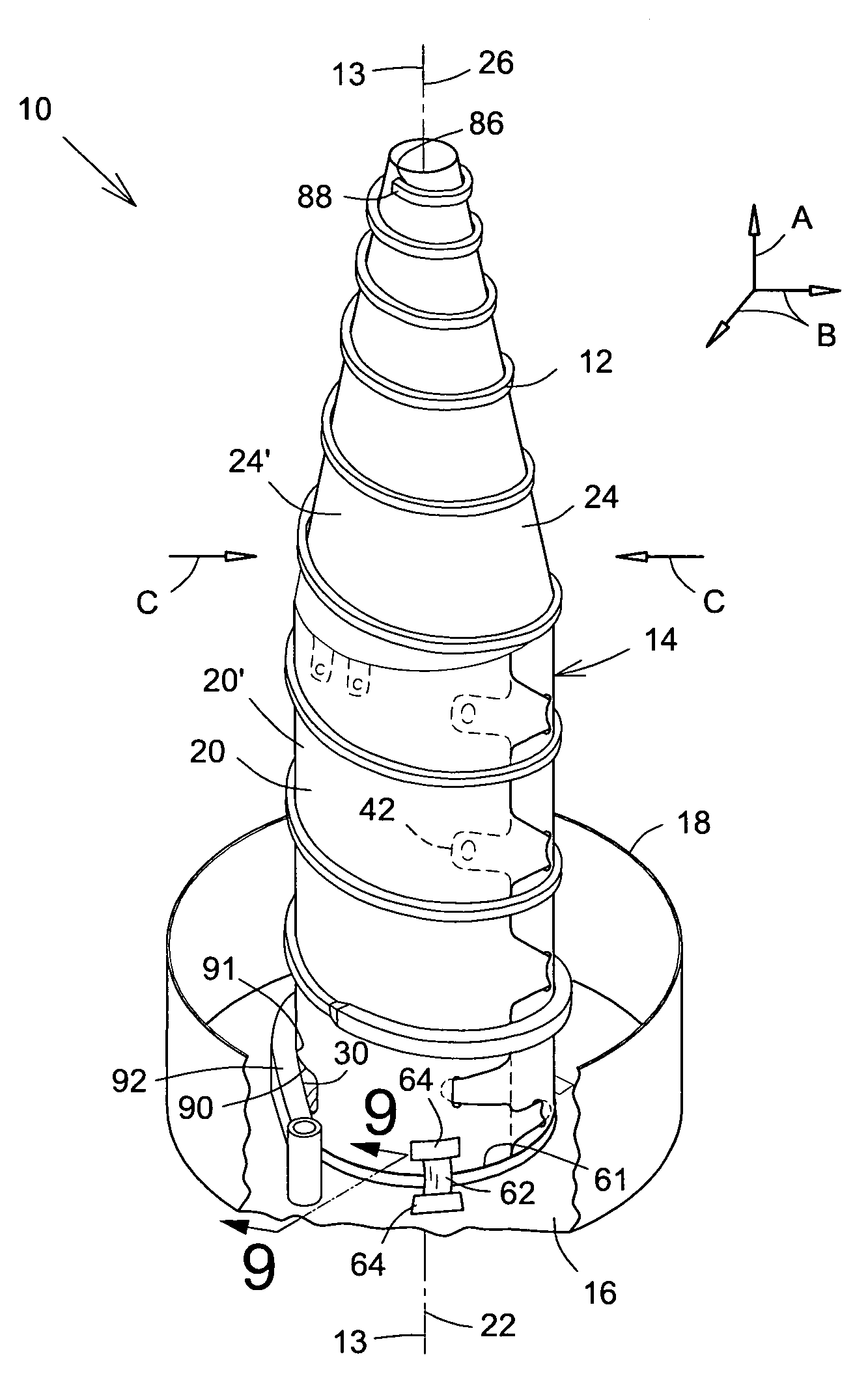
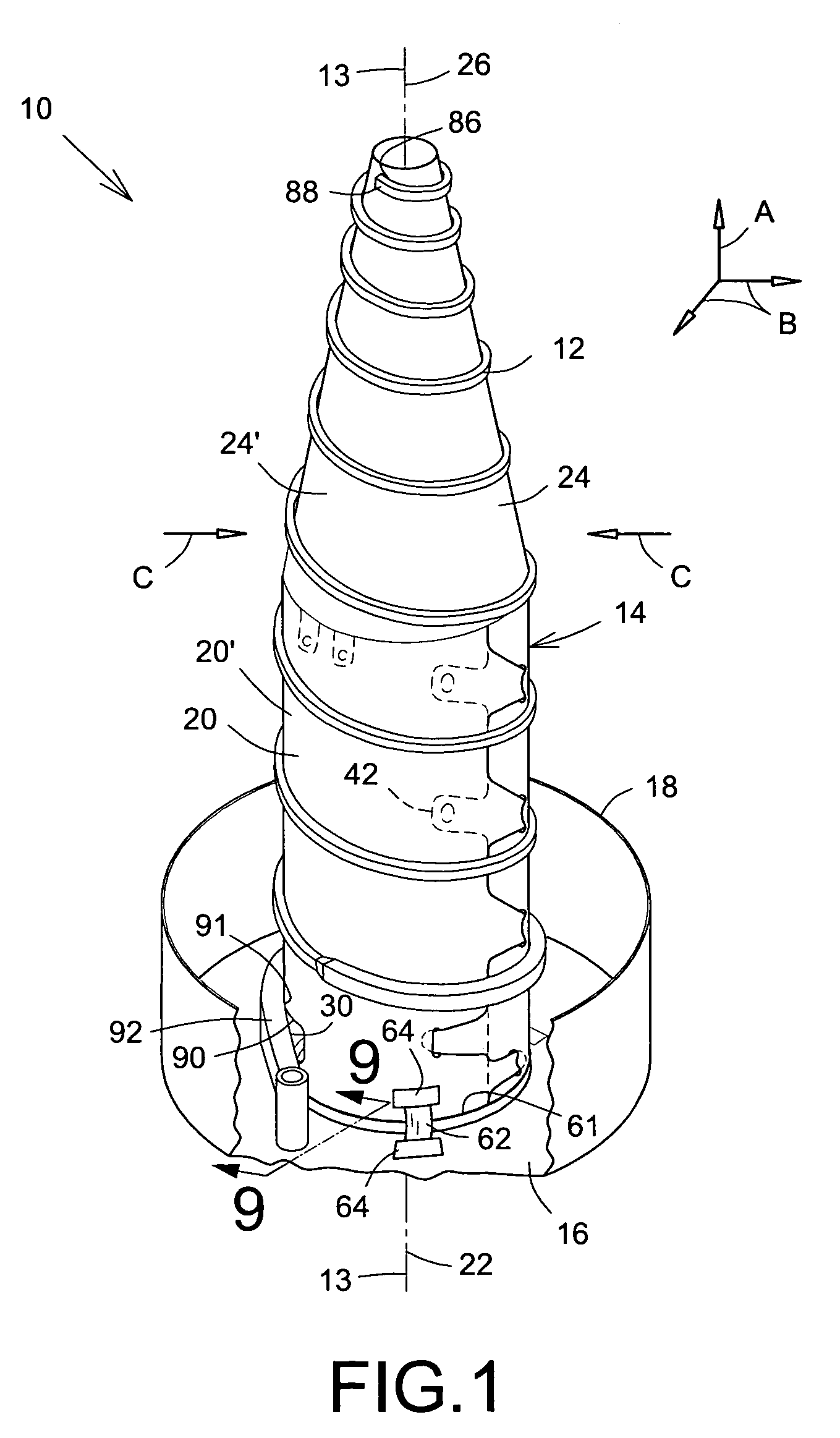
[0073]Referring to FIG. 1, there is schematically shown an embodiment of a helix antenna 10 in accordance with the present invention. The antenna 10 typically includes an electrical conductor or component 12 having a substantially helix shape and defining a helix axis 13, a helix support 14 and a mounting base 16 generally supporting the support 14 and the helix 12, and typically having a conventional cup shape 18. Although the present embodiment 10 is illustrated with one helical conductor 12, a plurality of conductors 12 could be used and mounted on the same support 14 without departing from the scope of the present invention.

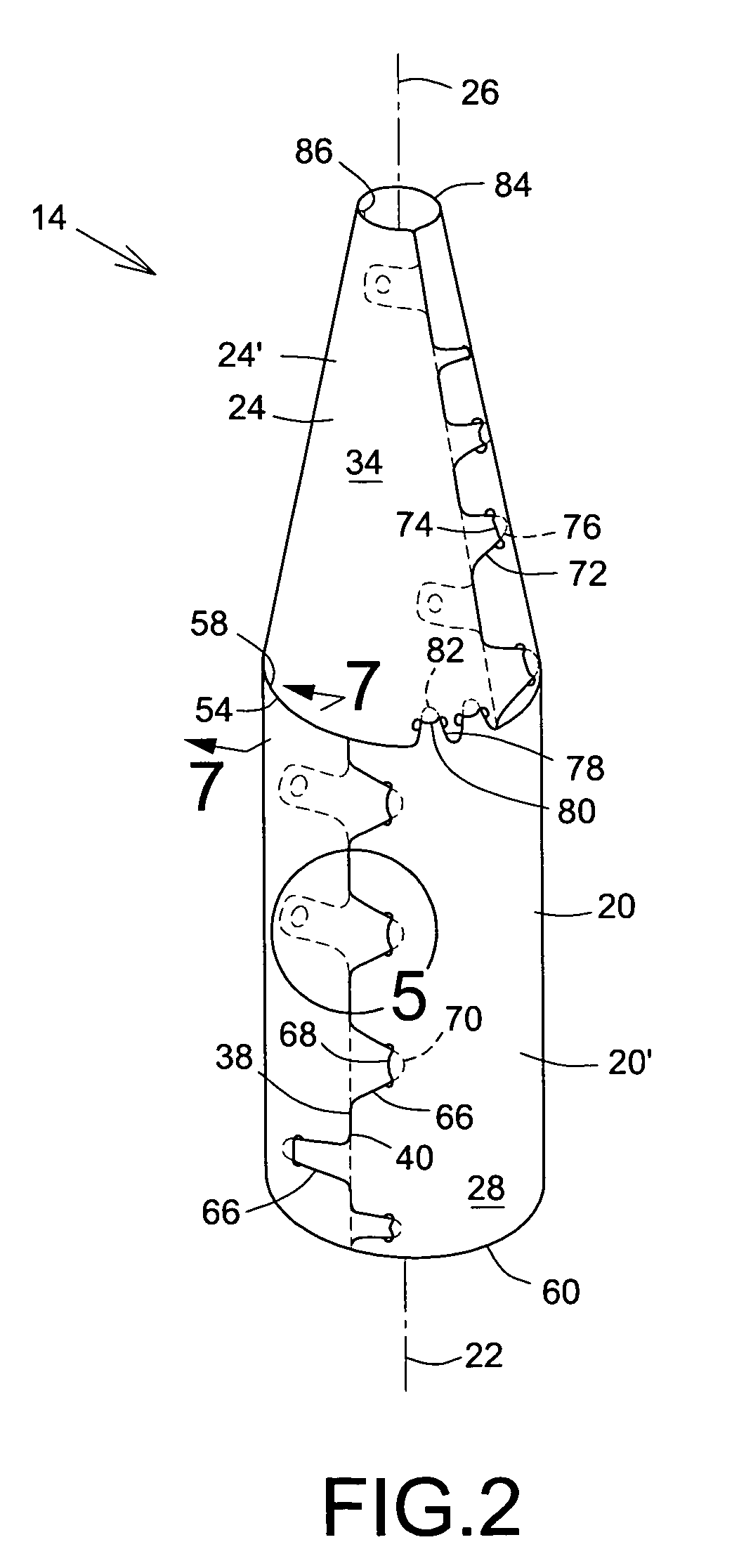
[0074]Referring more specifically to FIGS. 1 to 4, the helix support 14 is mounted on the mounting base 16 of the antenna 10. The helix support 14 includes a first or lower flexible sh...


PUM


Abstract

A helical antenna has a helix supported by a helix support. The helix support includes at least one piece of flexible sheet having its two surfaces covered with a layer antistatic material. The flexible sheet is curlable into a revolution surface configuration to form a revolution surface-shaped support section for at least partially supporting a portion of the helix component there around. A grounding mechanism electrically grounds the external sheet surface to the helix and the two sheet surfaces to one another when in the revolution surface configuration while a locking mechanism locks the flexible sheet in the revolution surface configuration. The combination of the helix and the flexible support renders the antenna structurally relatively rigid in all directions.

Description

CROSS-REFERENCE TO RELATED APPLICATION[0001]Priority of U.S. Provisional Application No. 60 / 479,228, filed on Jun. 18, 2003, is hereby claimed.FIELD OF THE INVENTION[0002]The present invention relates to the field of antennas and is more particularly concerned with a helical antenna and the manufacturing thereof.BACKGROUND OF THE INVENTION[0003]It is well known in the art to use antennas mounted on a structure to allow communication with equipment located at a distance away. More specifically in the aerospace industry, global coverage antennas, shaped beam antennas and omni-directional antennas are conventionally mounted on spacecraft structure to allow specific communications to and from the ground through a ground station on Earth. These types of antenna typically include at least one helix component wound around an elongated Radio-Frequency (RF) transparent support.[0004]Few examples of helical antennas are illustrated in the following publications:[0005]U.S. Pat. No. 3,573,840, ...

Claims


Application Information

Patent Timeline
IPC IPC(8): H01Q1/36H01Q11/08
CPCH01Q1/362H01Q11/083H01Q11/08
Inventor LAROUCHE, STEVESENECHAL, GERARDBUSSIERES, FRANCOISRICHARD, SYLVAINBOUVRETTE, ANDREMCDOUGALL, JOHNMOSS, GEOFFREY
Owner MACDONALD DETTWILER & ASSOC CORP
Learn More