Piezo-electric actuated multi-valve manifold

a multi-valve, actuated technology, applied in the direction of valve housing, valve operating means/releasing devices, transportation and packaging, etc., can solve the problems of reduced work capability of the solenoid, extremely difficult control of the valve operation in a predictable linear fashion, and raw electromagnetic field raw power, so as to prevent undesirable flow, save reagent volume, and improve dispensing accuracy

Inactive Publication Date: 2006-05-09
PARKER INTANGIBLES LLC
View PDF66 Cites 45 Cited by
  • Summary
  • Abstract
  • Description
  • Claims
  • Application Information

AI Technical Summary

Benefits of technology

[0009]The multi-valve manifold according to the present invention can house and provide fluid connections for multiple piezo actuated, direct acting valves. The current design of the valves is three-way on-off. These valves can be used for various applications including, by way of example and not limitation, mixing and diverting. In the current configuration, the manifold provides a common inlet port, a common exhaust port, and an outlet port unique to each valve. It also provides a single point for electrical connection and in some configurations the manifold will also house the system power supply and valve control. This same three-way valve configuration can be operated in a proportional mode for mixing or blending applications. In such applications, the common exhaust port, described above, would be used as a second common inlet port. Alteration of the flow can enable use for diverting applications. In support of mixing, blending or diverting, check valves can be incorporated to prevent undesirable flow.
[0010]A unique design feature of the multi-valve manifold pack is that the valve spacing is set at 4.5 mm. This tight spacing allows, for example, the valve to provide direct dispensing of analytical fluids. Such fluids can be transferred into titration wells that are currently spaced 4.5 mm apart in typical titration trays using, for example, a nozzle directly attached to the outlet ports of the manifold or minimal interface tubing from the valves to the wells. This can improve dispensing accuracy, save reagent volumes and improve dispensing times. Typical existing valve manifolds use 10 mm spacing, thus requiring complex valve mounting geometries and extensive tubing or manifolding to transfer the fluid being dispensed from the valve. The present invention provides for nozzles attached to the manifold on 4.5 mm pitch and in line with the valves located at 4.5 mm spacing from one another mounted on the manifold, i.e. the valve is inline and very close so that there is minimal “dead volume” from the valve to the dispensing orifice or nozzle.
[0011]Another unique feature of the valve is its high flow capacity within the 4.5 mm pitch spacing. At 80 psig the valve in the three-way configuration will flow approximately 50 standard liters per minute (slpm). Existing valves, even based on a 10 mm width, do not typically flow more than 20 lpm. Thus the valve of the present invention can, by way of example and not limitation, also be used very effectively to pilot much larger pneumatically actuated valves.

Problems solved by technology

In general, smaller solenoid based valves do not exist, because as the solenoid decreases in size, the work capability of the solenoid is reduced to the point where the solenoid is incapable of providing operation of the valve for the desired valve pressures and flow rates.
The issue is not merely the raw power of the electromagnetic field as the coil decreases, but rather the ability to control the operation of the valve in a predictable linear fashion is extremely difficult.
Further, a proportional valve is continually operating, thus typically requiring greater heat dissipation / handling ability than a simple on / off valve.
Further, the commercially available solenoid valves generally consume between 0.5 and 4.0 watts.
Other piezo valves have lower power consumption compared to such solenoid actuated valves, but none of the piezo valves have the desired level of flow and pressure capability on a direct acting basis in as narrow a size.

Method used


Image

  • Piezo-electric actuated multi-valve manifold
  • Piezo-electric actuated multi-valve manifold
  • Piezo-electric actuated multi-valve manifold

Examples


Embodiment Construction

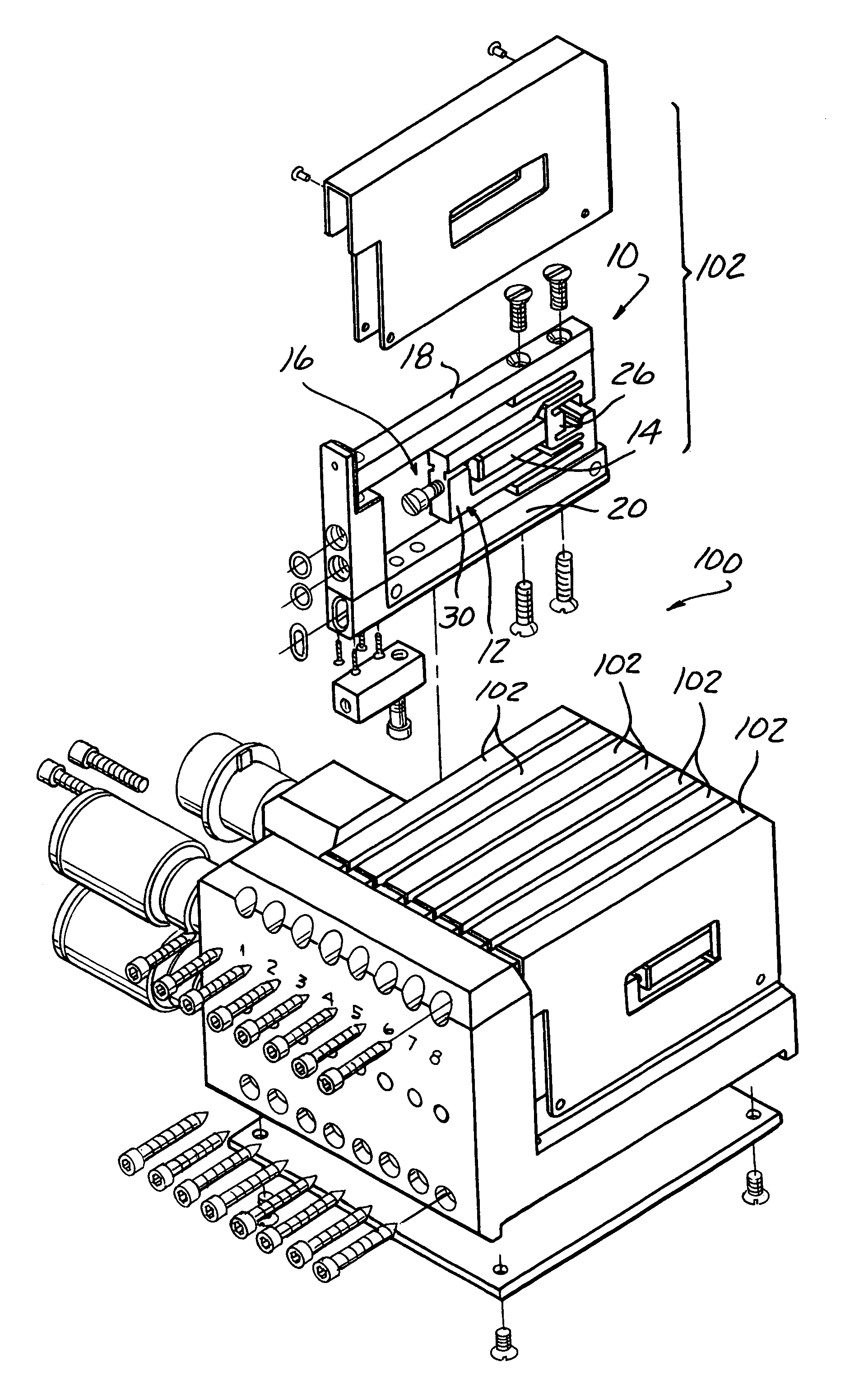
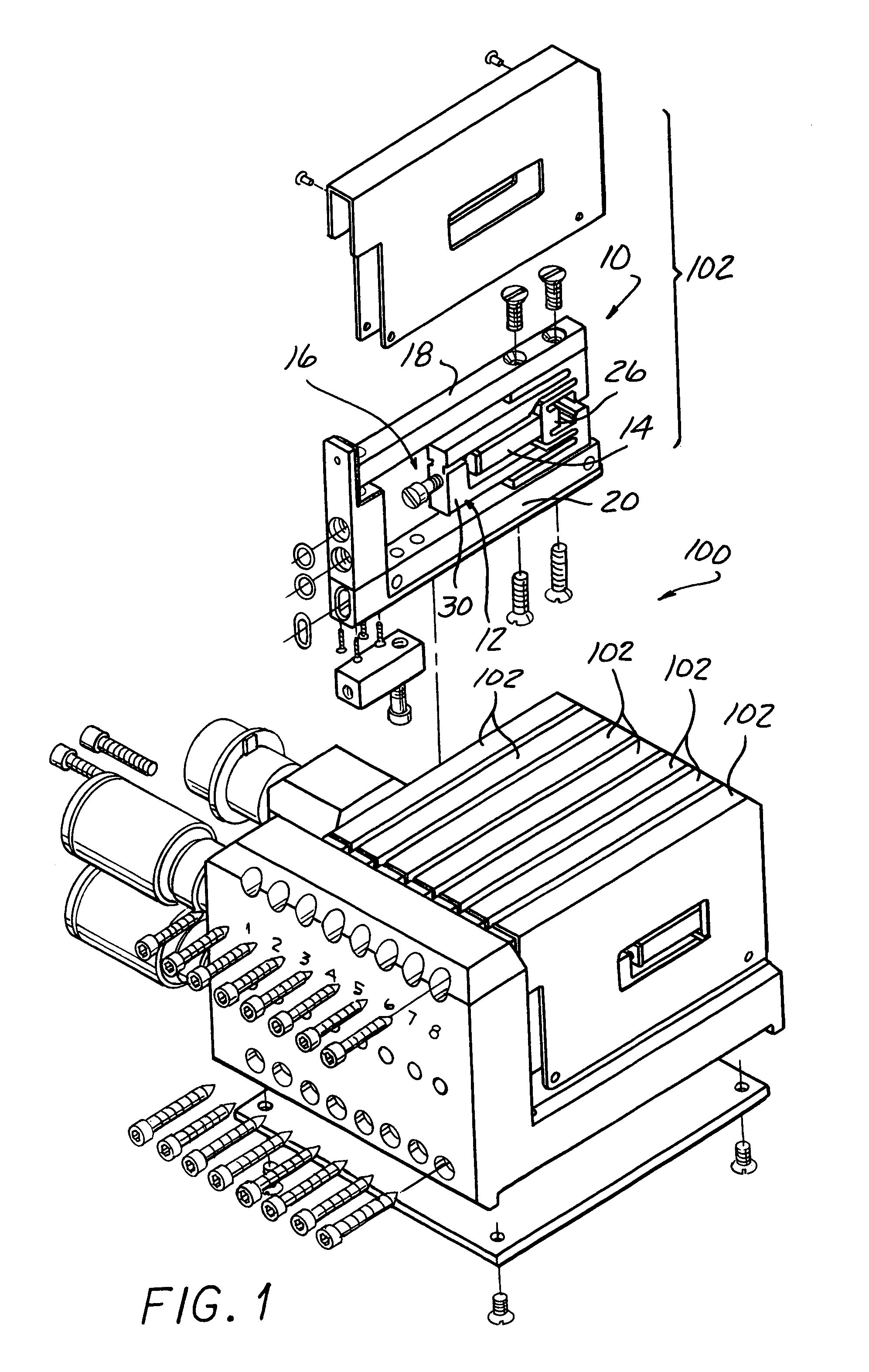
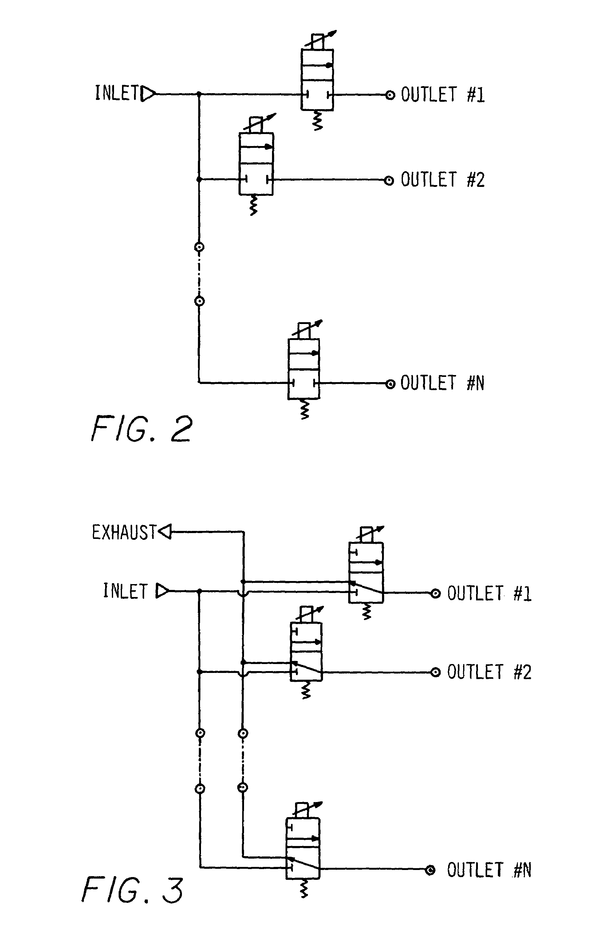
[0022]Referring now to FIGS. 1–3, the present invention includes a multi-valve manifold 100. Each valve 102 in the manifold 100 can be, by way of example and not limitation, 4.2 millimeters (mm) wide by 31 mm tall by 46 mm long. The narrow width of the actuator / valve combinations according to the present invention allows the actuator / valve combinations to be located on the manifold at a center-to-center spacing, or pitch, of 4.5 mm apart from one another in order to provide an advantageous titration tray dispensing embodiment discussed in greater detail below. The 4.2 mm width is believed to be narrower than any other “meso-scale” electrically actuated valve, and therefore unique in the industry. The closest known commercially available solenoid operated valve is 6 mm in diameter. Although electrically actuated valves smaller than 4.5 mm exist, the valves are much smaller, and are based on alternate construction and / or actuation techniques. In general, smaller solenoid based valve d...


PUM


Abstract

An apparatus controls flow of a fluid from at least one inlet port to at least one outlet port. A support has a rigid, non-flexible portion, at least one pivotable relatively rigid, non-flexible, folded-back arm portion extending from the rigid portion, at least one surface connected to folded-back arm portion for movement relative to the support, and a rigid, non-flexible force transfer member operably positioned for driving the pivotable folded-back arm portion with a loss of motion of less than 40%. An electrically operated actuator operably engages between the rigid portion and the force transfer member to pivot the folded-back arm portion in response to an electrical activation of the actuator. A manifold includes a fluid passage communicating with at least one valve seat and operably engageable with respect to at least one corresponding valve body for movement between a closed position and an opened position.

Description

CROSS-REFERENCE TO RELATED APPLICATIONS[0001]This application claims the benefit of U.S. provisional patent application Ser. No. 60 / 460,666 filed on Apr. 4, 2003, and is a continuation-in-part of U.S. patent application Ser. No. 10 / 107,951 filed Mar. 27, 2002 now U.S. Pat. No. 6,759,790 and a continuation-in-part of U.S. patent application Ser. No. 10 / 613,138 filed on Jul. 3, 2003.FIELD OF THE INVENTION[0002]The present invention relates to at least one piezo-electric actuated valve capable of two-way or three-way operation for on / off or proportional control of fluid passing between at least one inlet port and at least one outlet port of a fluid passageway.BACKGROUND OF THE INVENTION[0003]Commercially available solenoid operated valves typically are available in sizes down to a minimum 6 mm in diameter. Although valves smaller than 4.5 mm exist, the valves are much smaller, and are based on alternate construction and / or actuation techniques such as MEMS. In general, smaller solenoid...

Claims


Application Information

Patent Timeline
Patent Type & Authority Patents(United States)
IPC IPC(8): F16K11/10F16K27/00F16K31/00H01L41/09
CPCF16K31/006F16K27/003Y10T137/87877Y10T137/87885
Inventor MOLER, JEFFWOOZLEY, MARKBUGEL, JOHN
Owner PARKER INTANGIBLES LLC
Why Eureka
Try Eureka