Techniques for managing a set of cables

a technology for managing cables and cables, applied in the field of techniques, can solve the problems of affecting the operation of the support structure, affecting the service life of the cable, and requiring a significant amount of manual effort and time, and achieve the effect of preventing the stress on the cable end

Inactive Publication Date: 2006-05-09
EMC IP HLDG CO LLC
View PDF14 Cites 21 Cited by
  • Summary
  • Abstract
  • Description
  • Claims
  • Application Information

AI Technical Summary

Benefits of technology

[0014]In one arrangement, each bushing of the set of bushings defines (i) a respective aperture, as one of the set of cable ports, in an X-Y plane, and (ii) a wide-radius surface to substantially support a set of cables passing through that respective aperture in a Z-direction which is substantially perpendicular to the X-Y plane. Accordingly, the wide-radius surface of each bushing can operate as a support that prevents the cables from pinching or kinking (e.g., a preventative limit on the cable bend radius for fiber optic cables). Furthermore, in some applications, the bushings can provide strain relief to prevent placing stresses on the cable ends (e.g., to avoid damaging connectors at the ends of the cables).
[0015]In one arrangement, the cover portion of the access panel assembly substantially extends in the X-Y plane. In this arrangement, each bushing includes a flange portion having the wide-radius surface. At least part of that flange portion overlaps part of the cover portion in the X-Y plane. Due to such overlap, it is less likely that electromagnetic interference will escape from the chassis.
[0016]In one arrangement, the frame portion includes a rigid metallic edge that defines the frame opening. In this arrangement, each bushing of the set of bushings includes a rigid metallic structure which rigidly fastens to the rigid metallic edge of the frame portion (e.g., using rivots, welds, etc.). Accordingly, the bushings can be robustly and reliably mounted to the frame portion.
[0017]In one arrangement, the cable management system further includes cable ties which are configured to hold a set of cables in stable positions. Each cable tie is coupled to one of the chassis, the communications interface and the access panel assembly. The use of the cable ties provides an additional vehicle for positioning the cables within the cable management system in an orderly fashion.

Problems solved by technology

Unfortunately, there are deficiencies to using the above-described conventional electronic equipment rack components which require cables that run from the backs of the component housings.
Such operation may require a significant and painstaking amount of manual effort and time.
Additionally, during such operation, the technician runs the risk of scraping the sides of the cables against the plates or the housing walls (i.e., along the hole edges) and damaging the cables (e.g., tearing the insulation from the cables).
In extreme situations, some technicians may view the tasks of feeding the cables through the circular or oval-shaped holes as being too burdensome, and decide not to invest the time and effort to properly install the cables through such holes.
As an alternative, these technicians may simply run the cables through the open areas which are normally hidden by the plates, and leave the plates off of the housings thus omitting the EMI protection.
Furthermore, in the case where the manufacturer provides gaps along the edges of the plates so that the technicians can maneuver the cables through the edge-located gaps when mounting the plates to the housings, the cables can later brush against the plates.
In some situations, the force of the cables against the plates can be so severe (e.g., due to movement of the equipment rack caused by vibration, due to pulling on the other ends of the cables, etc.) that the plates inadvertently become dislodged from the chassis and no longer properly provide EMI protection.

Method used


Image

  • Techniques for managing a set of cables
  • Techniques for managing a set of cables
  • Techniques for managing a set of cables

Examples


Embodiment Construction

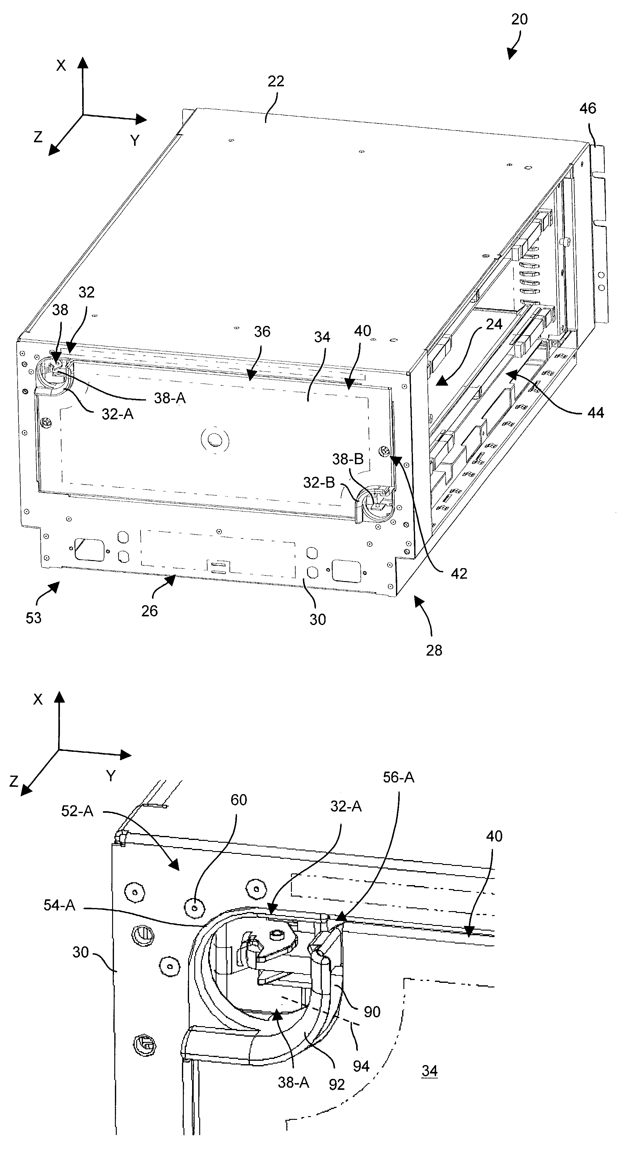
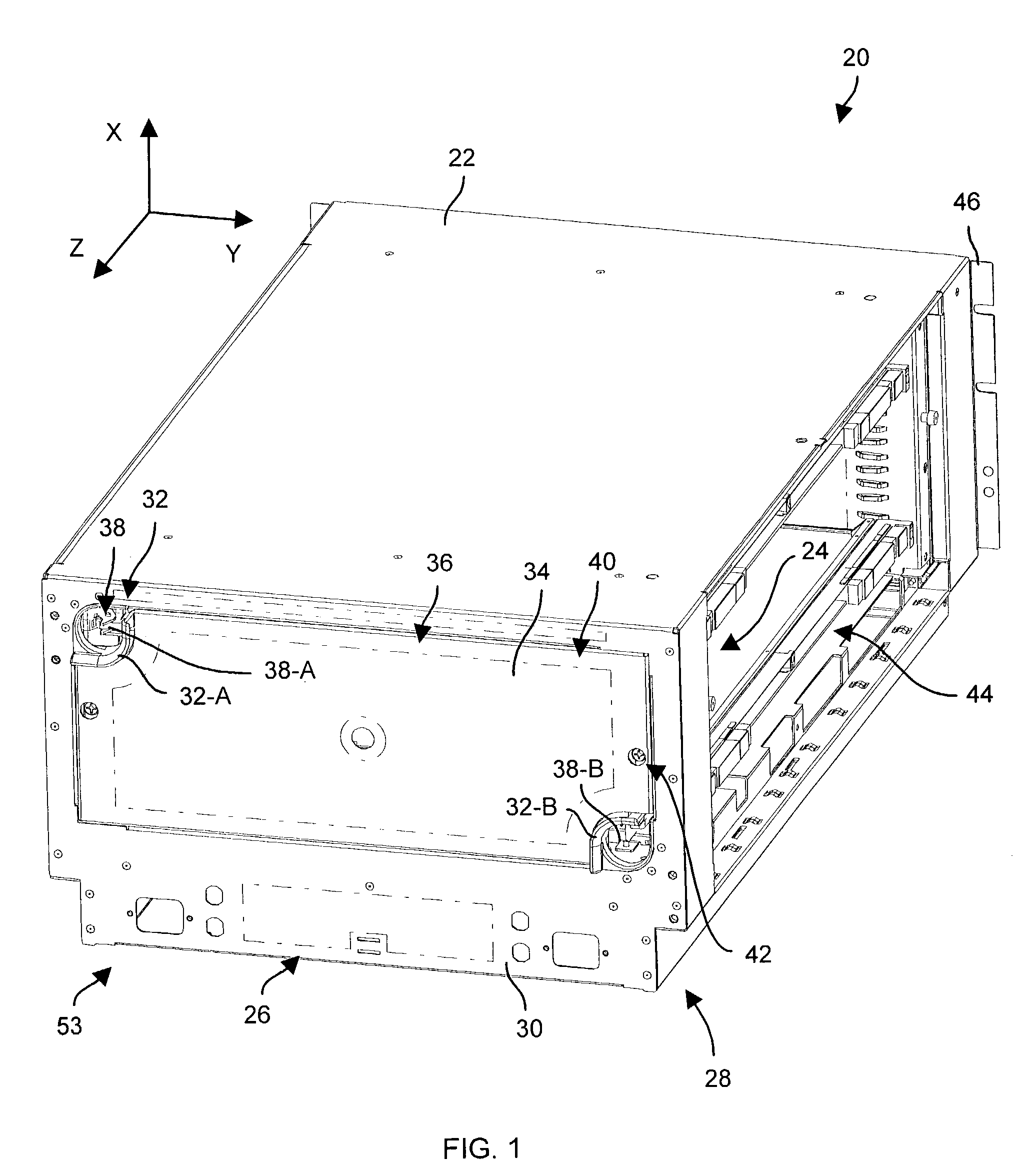
[0027]The invention is directed to techniques for managing a set of cables (e.g., fiber optic cables, electrical signal cables, combinations thereof, etc.) using a set of bushings that defines both a set of cable ports and an access port within a frame opening. Accordingly, the frame opening is well-suited for both locating cables (e.g., through the set of cable ports), as well as for other forms of access (e.g., manual access through the access port by a technician when plugging or unplugging cable connectors) in a well-organized manner.

[0028]FIG. 1 shows a cable management system 20 which is suitable for use by the invention. As will be explained below, the cable management system 20 is well-configured to manage a set of cables. The cable management system 20 includes a chassis 22, a communications interface 24 (illustrated by the arrow 24 in FIG. 1), and an access panel assembly 26. The communications interface 24 is disposed along a side 28 of the chassis 22. The access panel as...


PUM


Abstract

A cable management system has a chassis, a communications interface and an access panel assembly. The cable management system a chassis which is configured to hold a set of circuit boards. The communications interface is disposed adjacent a side of the chassis. The access panel assembly is coupled to the side of the chassis and is disposed adjacent the communications interface. The access panel assembly includes (i) a frame portion which defines a frame opening, (ii) a set of bushings coupled to the frame portion, the set of bushings defining a set of cable ports and an access port within the frame opening defined by the frame portion, and (iii) a cover portion which is configured to substantially cover the access port defined by the set of bushings.

Description

BACKGROUND OF THE INVENTION[0001]A typical electronic equipment rack includes a vertically extending frame which supports multiple components. Each component typically includes a housing, and electronic circuitry (e.g., a set of circuit boards, an array of disk drives, etc.) which is contained within that housing. Such an equipment rack is well-suited for supporting a variety of electronic systems such as a general purpose computer system, a data storage system, network equipment, test equipment, power supply equipment, as well as other types of electronic equipment.[0002]In general, component manufacturers for electronic equipment racks design the components such that (i) control and display functions are accessible at the fronts of the components (e.g., keyboards, control buttons, LEDs, CRTs, etc.), and (ii) cables connect to the backs of the components (e.g., power cords, communication lines, etc.). Accordingly, after installation of the components, a user can conveniently operat...

Claims


Application Information

Patent Timeline
Patent Type & Authority Patents(United States)
IPC IPC(8): A47F7/00
CPCH05K7/1425
Inventor CLAPROOD, EDWARD J.CAVANAUGH, BARRY
Owner EMC IP HLDG CO LLC
Why Eureka
Try Eureka