Fuel feeding pipe

a technology of fuel feeding pipe and hose connection, which is applied in the direction of hose connection, liquid handling, packaging goods type, etc., can solve the problems of assembling processes, increasing the number of parts, and affecting the quality of the finished product, and achieves excellent slip-off prevention effect, stable connection condition, and similar cross-sectional shape

Inactive Publication Date: 2006-05-09
BRIDGESTONE CORP +1
View PDF21 Cites 19 Cited by
  • Summary
  • Abstract
  • Description
  • Claims
  • Application Information

AI Technical Summary

Benefits of technology

[0011]The fuel feeding pipe according to the present invention is formed by fitting the outer fitting pipe connected to the first feed oil pipe around the inner fitting portion of the second feed oil pipe. In this fuel feeding pipe, the outer fitting pipe is tightened with respect to the inner fitting portion by the tightening belt, and hermeticity of the fuel feeding pipe is improved by inserting seal rings between the outer fitting pipe and the inner fitting portion, thereby restraining the permeation of the fuel through the wall of the of the fuel feeding pipe to the outside thereof. The structure of connecting of the first feed oil pipe and second feed oil pipe by fitting one into the other can remove the pipes easily. At the same time, a slip-off of the outer fitting pipe from the inner fitting portion can be prevented owing to the friction of the seal rings occurring between the outer fitting pipe and the inner fitting portion in an engaged state. The seal rings may be fitted in corresponding ring fitting grooves provided in the inner fitting portion. The depth of each of the ring fitting grooves is set smaller than the thickness of each of the seal rings.
[0013]The inner fitting portion, the outer fitting pipe and the tightening belt are brought into close contact with each other by a tightening force of the tightening belt positioned with covering the first and the second feed oil pipes, and thereby the mutually connected condition in the engaged region of the pipe can be maintained. In order to attain a more stable connected condition, it is preferable to develop the structural close contact of these three parts with one another. To be concrete, the inner fitting portion, the outer fitting pipe and the tightening belt are provided with an inner fitting tapering section, an outer fitting tapering section and a tightening tapering section, which have a similar cross-sectional shape, respectively. It is preferable that the outer fitting pipe is tightened against the inner fitting portion by the tightening belt with utilizing the tapering sections brought into surface contact with one another. In this case, when an angle of inclination of these tapering sections is set to a friction angle, an excellent slip-off preventing effect can be displayed.
[0014]The tightening belt may be formed by a ring spring using spring steel. This tightening belt is set on the outer feed oil pipe by bolting the opposed flanges of the belt. In order to obtain the above-mentioned slip-off preventing effect more reliably, the present invention provides a stepped annular portion on the outer fitting pipe or the inner fitting portion and a slip-off preventing annular portion on the tightening belt, so that the slip-off preventing annular portion are engaged with the stepped annular portion. Owing to a mutual effect of the slip-off preventing annular portion and tapering sections, the loosening and displacement of the tightening belt due to the vibrations of an automobile are prevented, and a more reliable hermeticity of the fuel feeding pipe according to the present invention is thereby secured. Since the loosening and displacement of the tightening belt also cause ignition by fuel leakage, it is important the slip-off preventing effect of the tightening belt as an important security component.
[0015]Further, the provision of the displacement preventing structure on the tightening belt leads to the reliable determination of installing positions of each parts in the assembling process. It contributes to the attainment of a high assembling operation efficiency.
[0016]Furthermore, this also means that it is hard that the tightening belt loosened during replacement operation of a feed oil pipe or a fuel tank slips off from the outer fitting pipe or the inner fitting portion. It becomes the higher efficiency of carrying put the maintenance operation.
[0017]When a slip-off preventing annular portion in one is provided on the tightening belt, the slip-off preventing annular portion may be deformed to obstruct the diametrical contraction of the tightening belt during tightening the tightening belt with respect to the outer fitting pipe. Therefore, there is the possibility that the tightening of the belt becomes insufficient. Under the circumstances, a plurality of slits are preferably provided in this slip-off preventing annular portion. As a result, the spaces between the slits are narrowed without deforming the slip-off preventing annular portion during a belt tightening operation smoothly, so that the belt can be tightened easily and reliably on the outer fitting pipe.

Problems solved by technology

However, this rubber or resin pipe has the property of permeating fuel vapor through a wall thereof, and causes atmospheric pollution to occur.
First, the case of the fuel feeding pipe formed by connecting the flange provided on an end portion of the first feed oil pipe to the fuel tank in a surface contacting state will be described. Since it becomes necessary that a packing is provided between the flange and fuel tank so as to secure hermeticity thereof, the durability of the packing becomes a problem. In addition, a whirl-stop member, such as a spring washer for preventing the loosening of the packing also becomes necessary, and this causes an increase in the number of parts and the number of assembling processes. Moreover, due to the structure for fixing the first feed oil pipe to the fuel tank, the transferring of the first feed oil pipe to an assembly line when a specially long first feed oil pipe is used is rendered difficult, and the replacement of parts of the first feed oil pipe also becomes difficult.
The loosening and separation of the joint causes the leakage of a fuel and in its turn the ignition of the fuel.
However, the use of a solid joint in which neither the loosening nor the separation thereof occurs causes an increase in the number of parts and the number of assembling processes, and, moreover, renders the replacement of parts difficult.

Method used


Image

  • Fuel feeding pipe
  • Fuel feeding pipe
  • Fuel feeding pipe

Examples


Embodiment Construction

[0026]Preferred embodiments of the present invention will now be described with reference to the drawings.

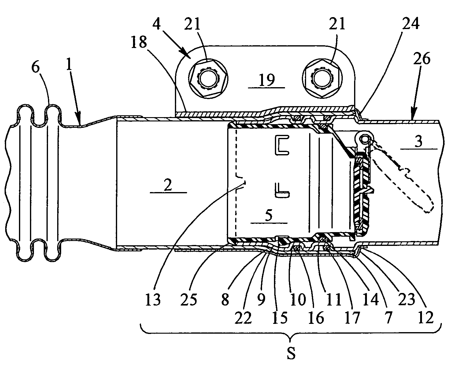
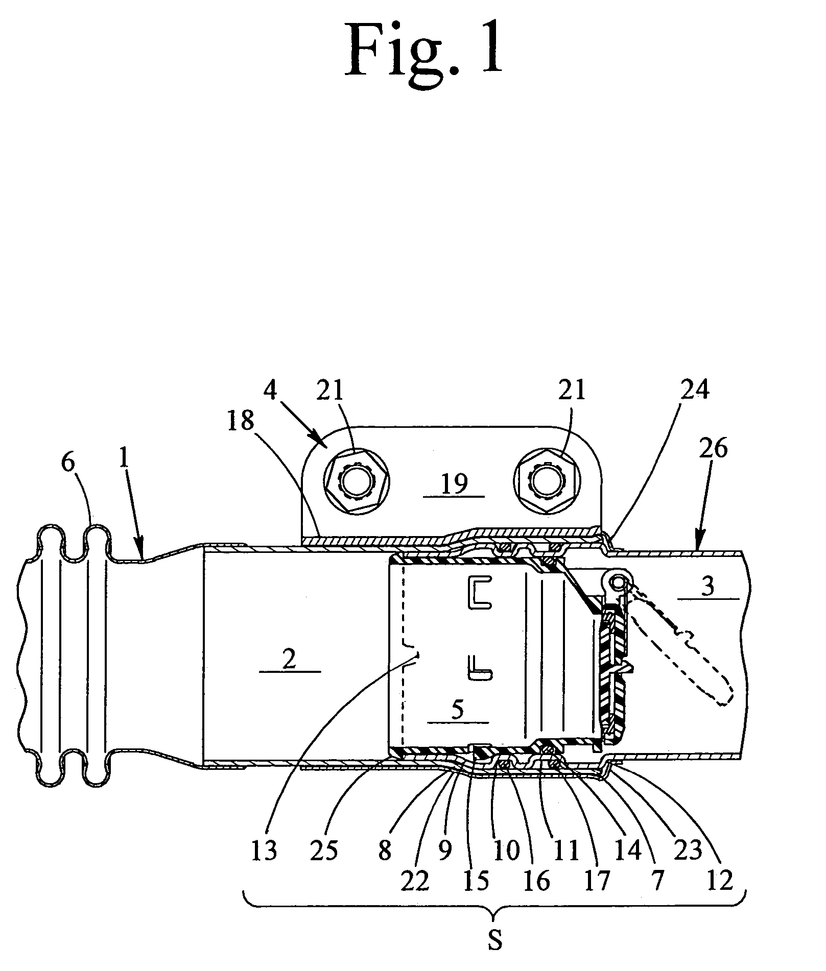
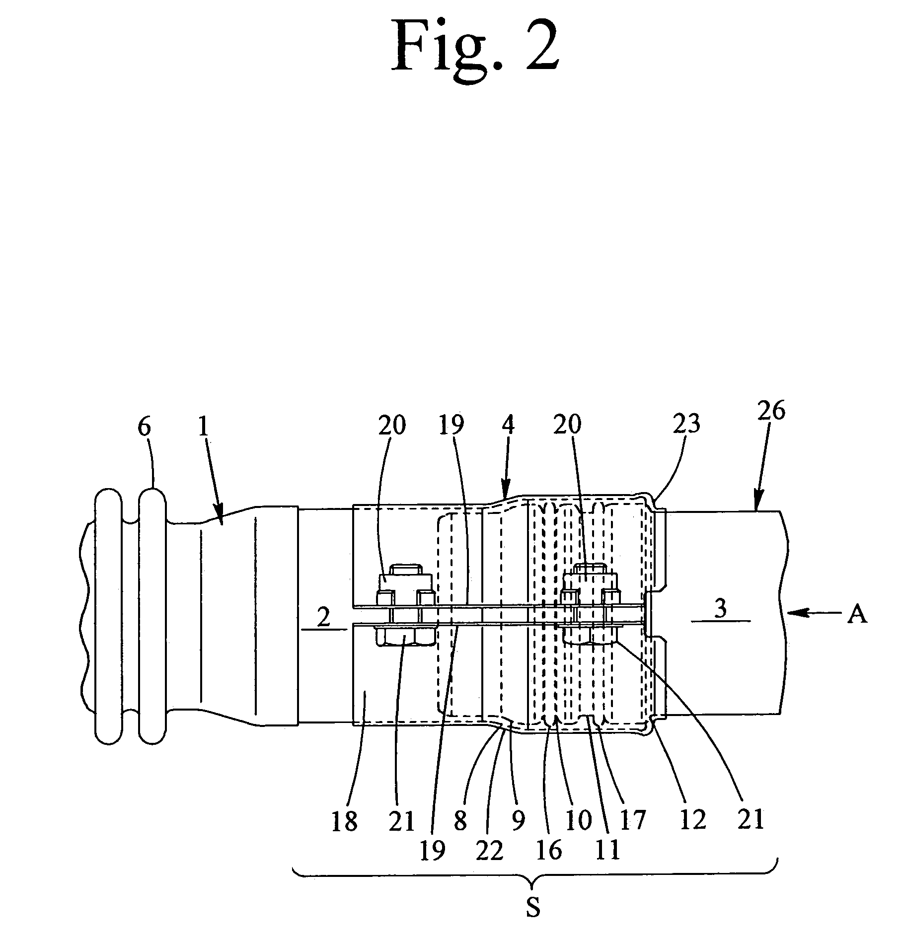
[0027]A fuel feeding pipe in this embodiment is formed as shown in FIG. 1 onward, by connecting an independently made outer fitting pipe 2 to a rear end of a first feed oil pipe 1, providing an inner fitting portion 3 on a front end portion of a second feed oil pipe 26 projecting from a fuel tank (not illustrated), engaging the outer fitting pipe 2 and inner fitting portion 3 with each other, and tightening the outer fitting pipe 2 in an engaged region S by a tightening belt 4 from the outside thereof.

[0028]It is free to assign either the outer fitting pipe 2 or the inner fitting portion to the first feed oil pipe 1, or second feed oil pipe 26. Thus, the engaging relation between these parts may be set reversely with respect to that between such parts in this embodiment, as shown in FIG. 7. However, since a check valve 5 is provided in the fuel feeding pipe in this embodiment, t...


PUM

PropertyMeasurementUnit
diameteraaaaaaaaaa
temperatureaaaaaaaaaa
widthaaaaaaaaaa

Abstract

A fuel feeding pipe having a first feed oil pipe extending from an oil filler port, a second feed oil pipe projecting from a fuel tank, and a tightening belt for connecting and tightening these oil pipes together, comprising an outer fitting pipe provided to the first feed oil pipe, and an inner fitting portion provided to the second feed oil pipe having low-temperature resisting and ozone resisting seal rings fitted therearound. The fuel feeding pipe is formed in one body by fitting the outer pipe around the inner fitting portion having the seal rings, then tightening the tightening belt fitted over at least the engaged region of the outer fitting pipe and the inner fitting portion. The invention achieves the minimization of a fuel permeation, high hermeticity without influences from various environments, the promotion of efficiency of replacement operation, and the vibration and impact resisting connection of the pipes.

Description

BACKGROUND OF THE INVENTION[0001]1. Field of the Invention[0002]This invention relates to a fuel feeding pipe formed by connecting together a first feed oil pipe which is a conduit extending from an oil filler port of an automobile and a second feed oil pipe which is a conduit projecting from a fuel tank.[0003]2. Prior Art[0004]General fuel feeding pipes for an automobile have been formed by manufacturing separately a conduit (hereinafter defined as a first feed oil pipe) extending from an oil filler port and a conduit (hereinafter defined as a second feed oil pipe) projecting from a fuel tank, and then connecting the resultant two feed oil pipes together during an installation process of the feed oil pipes to a vehicle body. In this fuel feeding pipe, the first and second oil pipes are connected together via a rubber or a resin pipe for the purpose of setting free the arrangement relation between the two feed oil pipes and of preventing the influence of vibrations of the fuel tank ...

Claims


Application Information

Patent Timeline
Patent Type & Authority Patents(United States)
IPC IPC(8): F16L25/00F16K15/03B60K15/04B60K15/01F02M37/00F16L21/06
CPCF16L21/065F16K15/03Y10T137/7855Y10T137/86324
Inventor KENMOTSU, TORUYOSHIDA, HIROSHIGOTO, HIROSHI
Owner BRIDGESTONE CORP
Why Eureka
Try Eureka