Method of infrared thermography

Inactive Publication Date: 2006-05-09
AIR FORCE THE US SEC THE
View PDF13 Cites 48 Cited by
  • Summary
  • Abstract
  • Description
  • Claims
  • Application Information

AI Technical Summary

Benefits of technology

[0018]Advantageously, the method of infrared thermography of the present invention quickly and accurately provides film cooled heat transfer coefficient values and film effectiveness values from a single test. This enables the turbine designer to accurately predict the overall effectives of proposed film cooling elements. The method of the present invention avoids the expensive use of thermographic liquid crystals to

Problems solved by technology

A competing consideration for the turbine designer is the fact that diversion of pressurized air from the compressor section for cooling purposes decreases the overall efficiency of the engine.
Such experimentation is costly, both in terms of expenditure of time and money and obviously, any reduction in these costs by improving testing techniques would be desirable.
This approach proved problematic, however, due to difficulties associated with obtainin

Method used


Image

  • Method of infrared thermography
  • Method of infrared thermography
  • Method of infrared thermography

Examples


Embodiment Construction

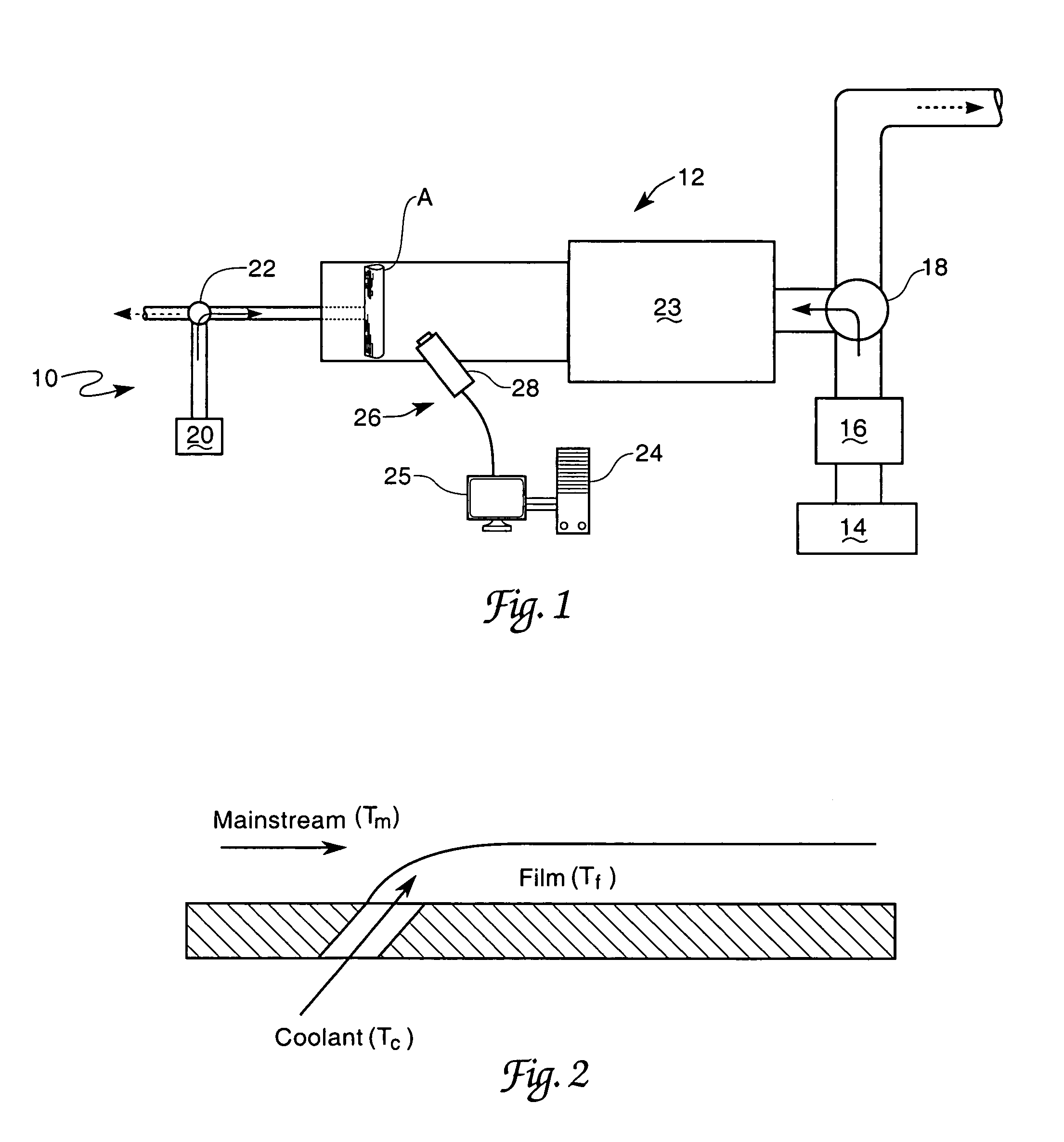
[0023]In accordance with the present invention, a method of infrared thermography for simultaneously determining film cooled heat transfer coefficients and film effectiveness values from a single test is described. As shown in FIG. 1, a typical test system 10 suitable for performing the method of the present invention is presented.

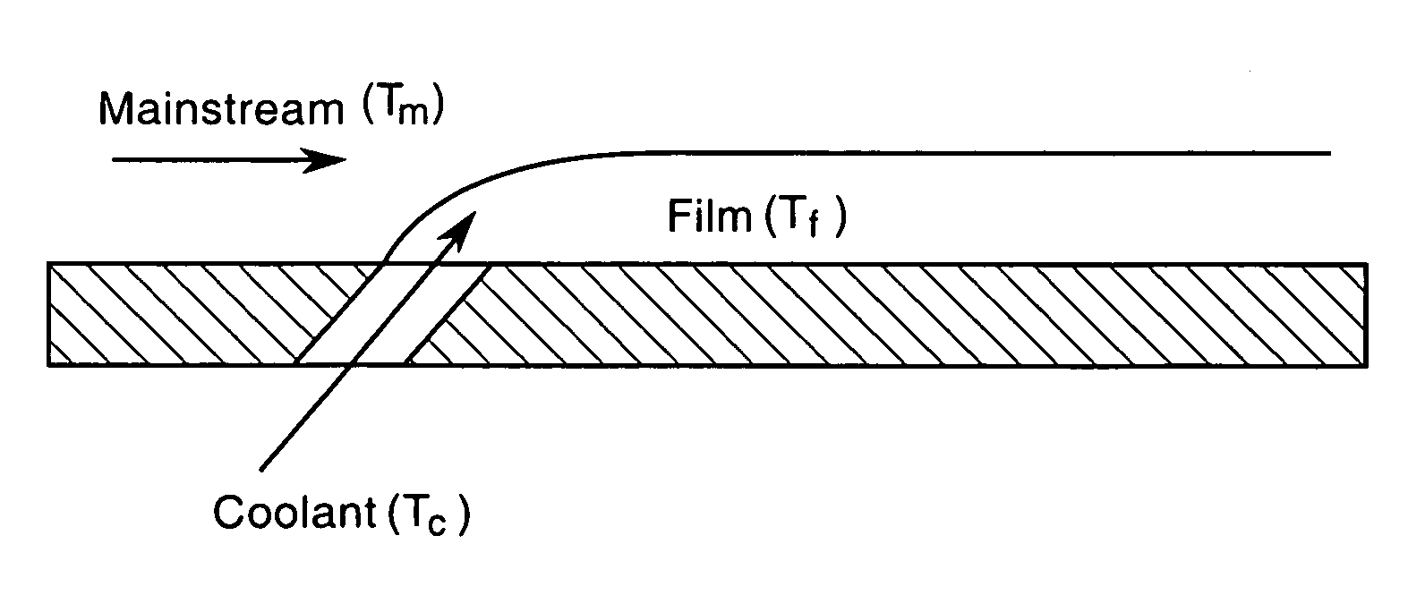
[0024]FIG. 2 is a diagrammatic representation of typical film cooling hole situation. The mainstream is the air coming over the wall and the temperature of the flow is indicated as mainstream temperature (Tm). The coolant temperature (Tc) is the temperature before injection through the hole. After injection, the mainstream and coolant mix and produce the local film temperature (Tf). The film temperature Tf is closer to coolant temperature immediately after the injection hole and then degrades as the coolant coverage decreases downstream and ultimately approaches the value of the mainstream temperature. Film effectiveness (η) is the non-dimensional temperat...


PUM


Abstract

A method of infrared thermography is described. The invention utilizes a high resolution infrared thermography system and associated computer in conjunction with a test chamber to determine heat transfer coefficients and film effectiveness values from a single test.

Description

RIGHTS OF THE GOVERNMENT[0001]The invention described herein may be manufactured and used by or for the Government of the United States for all governmental purposes without the payment of any royalty.BACKGROUND OF THE INVENTION[0002]The present invention relates generally to infrared thermography and more particularly to an infrared thermography method for determining film cooled heat transfer coefficients and film effectiveness from a single test.[0003]Film cooling is used extensively in modern gas turbines to cool hot gas path components. Film cooling is effected by injecting a cooler fluid onto the hotter surface through holes or slots provided within the surface of the turbine blades or vanes. As high performance turbine engine technologies advance, turbine inlet temperatures are raised to higher and higher values to achieve higher thermal efficiency. These higher temperatures necessitate effective film cooling to protect the turbine components. A competing consideration for th...

Claims


Application Information

Patent Timeline
IPC IPC(8): G01N25/72G01K17/10
CPCG01N25/72G01J2005/0081G01N25/18G01J5/48
Inventor OU, SHICHUANEKKAD, SRINATH V.RIVIR, RICHARD B.
Owner AIR FORCE THE US SEC THE
Why Eureka
Try Eureka