
Water intake and transmission system

a transmission system and water intake technology, applied in the direction of marine propulsion, vessel parts, vessel construction, etc., can solve the problems of reduced hull resistance, limited boat performance, and substantial drawbacks in the design of most jet units incorporated in most jet boats

Inactive Publication Date: 2006-05-09
DUAL DRIVE SYST
View PDF9 Cites 2 Cited by
  • Summary
  • Abstract
  • Description
  • Claims
  • Application Information

AI Technical Summary

Benefits of technology

[0009]The water intake and transmission system can be readily incorporated into the construction of new boats, as well as installed as a retrofit into existing boats. In this respect, the water intake need only be installed in place of an existing water intake with the housing having dual jet units mounted thereon coupled to such water intake. The driveshaft is operatively connected to the transmission system to thus enable both jet units to be simultaneously driven thereby.

Problems solved by technology

Additionally, the lack of exposed propeller eliminates impact damage or snags that can occur with protruding propulsion gear, as well as substantially reduces hull resistance insofar as the jet intake is generally flush with the hull bottom.
Despite such advantages, however, substantial drawbacks still exist with respect to the design of most jet units incorporated within most jet boats.
In such arrangement, the performance of the boat is limited by the jet unit generating the water jet propulsion.
Indeed, such drawbacks continue to exist despite substantial advances that have been made in jet unit design.
As a consequence, virtually all jet boats currently in use, despite the engine capacity to do so, suffer from suboptimal fuel efficiency, lesser responsiveness, and lesser ability to pull heavier loads than could be attained if the water jet propulsion generated by the jet unit were commensurate with engine capacity.

Method used


Image

  • Water intake and transmission system
  • Water intake and transmission system
  • Water intake and transmission system

Examples


Embodiment Construction

[0017]The detailed description set forth below is intended as a description of the presently preferred embodiment of the invention, and is not intended to represent the only form in which the present invention may be constructed or utilized. The description sets forth the functions and sequences of steps for constructing and operating the invention. It is to be understood, however, that the same or equivalent functions and sequences may be accomplished by different embodiments and that they are also intended to be encompassed within the scope of the invention.

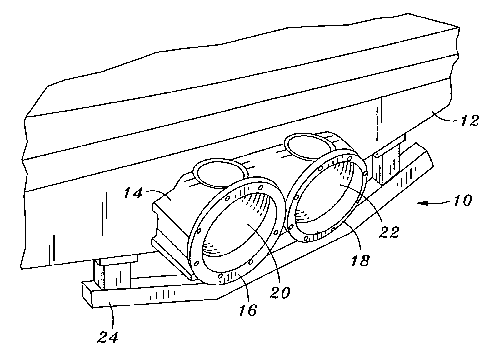
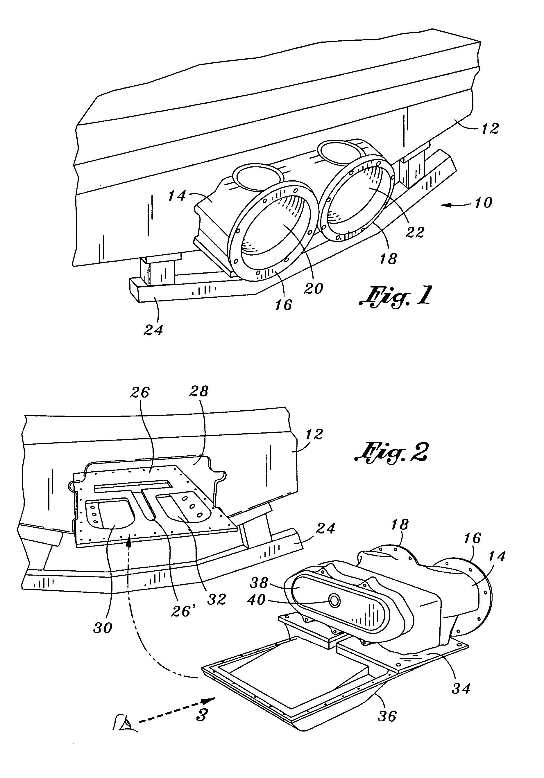
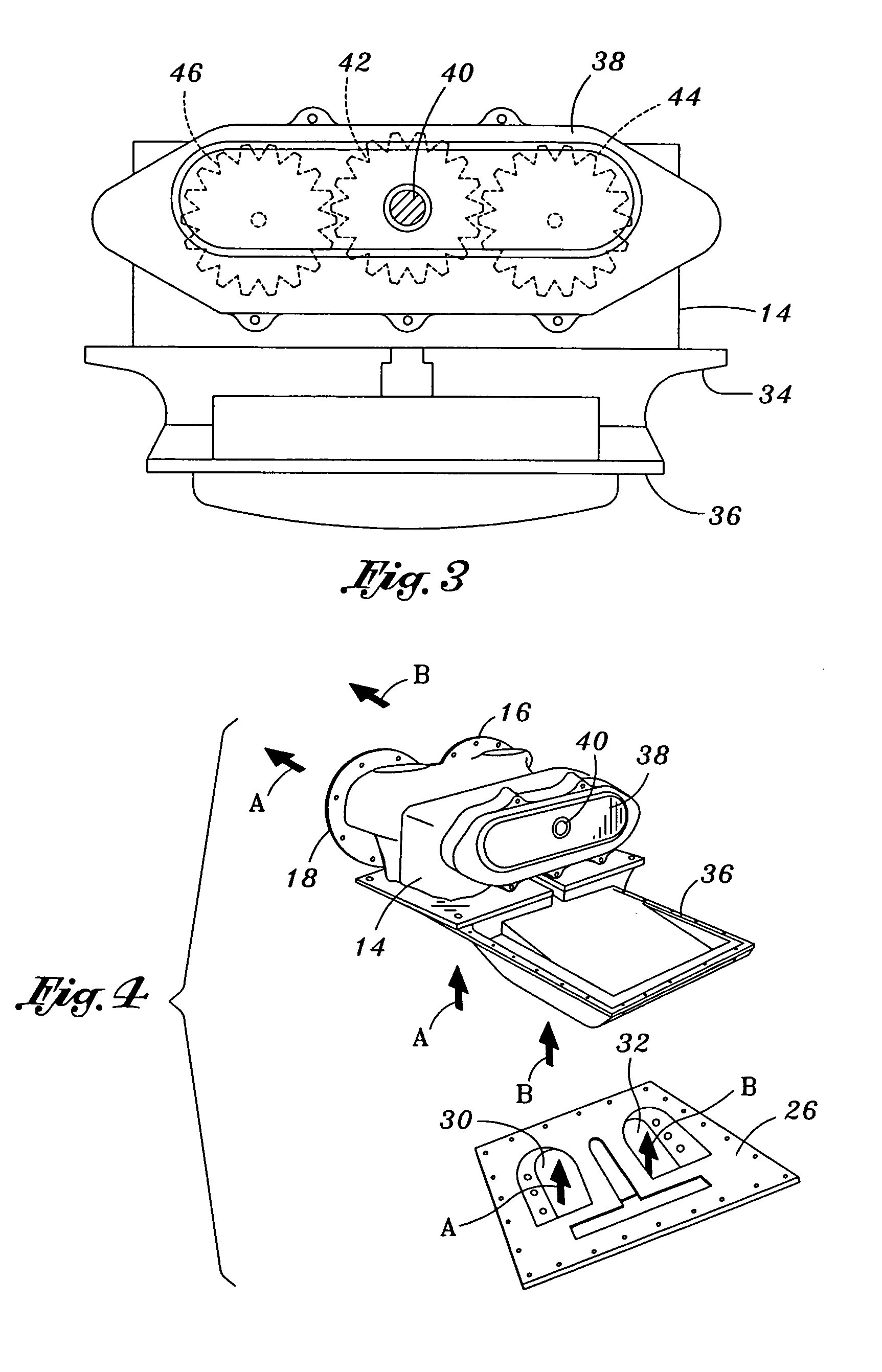
[0018]Referring now to the figures, and initially to FIG. 1, there is shown a dual nozzle water jet propulsion system 10 as provided by a novel water intake and transmission constructed in accordance with the preferred embodiment of the present invention, discussed below. As illustrated, the dual jet unit outputs are characterized by first and second output nozzles 16, 18 emanating from a housing 14, the latter mounted upon the...


PUM


Abstract

A water intake and transmission system for simultaneously driving dual jet units of a jet boat. According to a preferred embodiment, the water intake includes dual channels to allow the uptake of dedicated streams of water. Mounted to the intake is a housing having first and second jet units encased therein wherein each jet unit receives a dedicated stream of water from a respective channel of the water intake. A transmission is operatively coupled to each respective jet unit and is further connected to the driveshaft of the boat engine, preferably via gears, belt-drives, and / or chain drives, that is operative to simultaneously drive both jet units from a single driveshaft.

Description

CROSS-REFERENCE TO RELATED APPLICATIONS[0001]The present application is a continuation-in-part of U.S. patent application Ser. No. 09 / 995,980, filed Nov. 15, 2001 now U.S. Pat. No. 6,626,713 by Harold Bruce, et al., entitled WATER INTAKE AND TRANSMISSION SYSTEM.STATEMENT RE: FEDERALLY SPONSORED RESEARCH / DEVELOPMENT[0002]Not ApplicableBACKGROUND OF THE INVENTION[0003]Water pump-propelled boats or “jet boats” are well-known in the art. In this regard, such boats comprise a normal boat fitted with an engine to drive a water pump or “jet unit” that draws water from an intake formed in the bottom of the boat and thereafter discharges the water through the transom of the boat at a high velocity. To achieve that end, the jet unit typically is provided with an impeller and stator which increases the pressure of the water flow drawn in from the intake and discharges the same via a nozzle formed at the back of the jet unit as a high velocity jet stream. The jet unit is propelled by a jet-driv...

Claims


Application Information

Patent Timeline
Patent Type & Authority Patents(United States)
IPC IPC(8): B63H11/00B63H11/08B63H23/06
CPCB63H11/08B63H23/06B63H2023/065B63H2023/062B63H2011/008
Inventor BRUCE, HAROLD
Owner DUAL DRIVE SYST
Learn More