
LED epiwafer pad manufacturing process & new construction thereof

a manufacturing process and epiwafer technology, applied in the direction of basic electric elements, electrical equipment, semiconductor devices, etc., can solve the problems of peeling problem, comparatively higher production cost incurred in the evaporation process, poor efficiency of precious metal use, etc., to improve the roughness of the surface of the electroplated pad, improve the adhesion, and increase the interfacial bonding strength

Inactive Publication Date: 2008-10-30
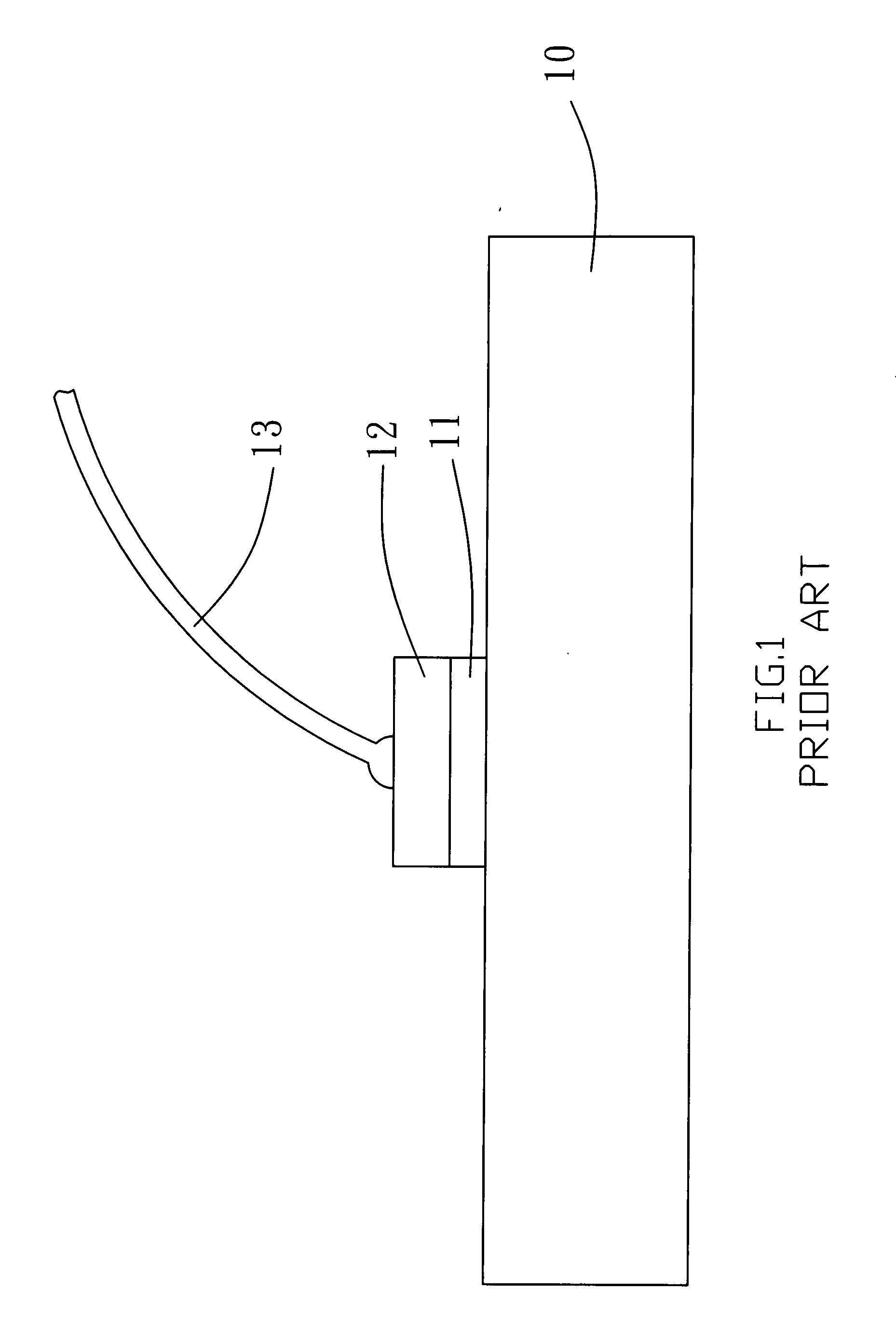
FUPO ELECTRONICS CORP
View PDF0 Cites 12 Cited by
  • Summary
  • Abstract
  • Description
  • Claims
  • Application Information

AI Technical Summary

Benefits of technology

[0023]Taking the plasma for instance, the first metal surface of the epiwafer is plasma processed; the second metal layer is electroplated on the surface of the first metal layer; and the pad pattern is formed by the photolithography and metal etching processes to To reliably improve the adhesion between the pad and the epiwafer.
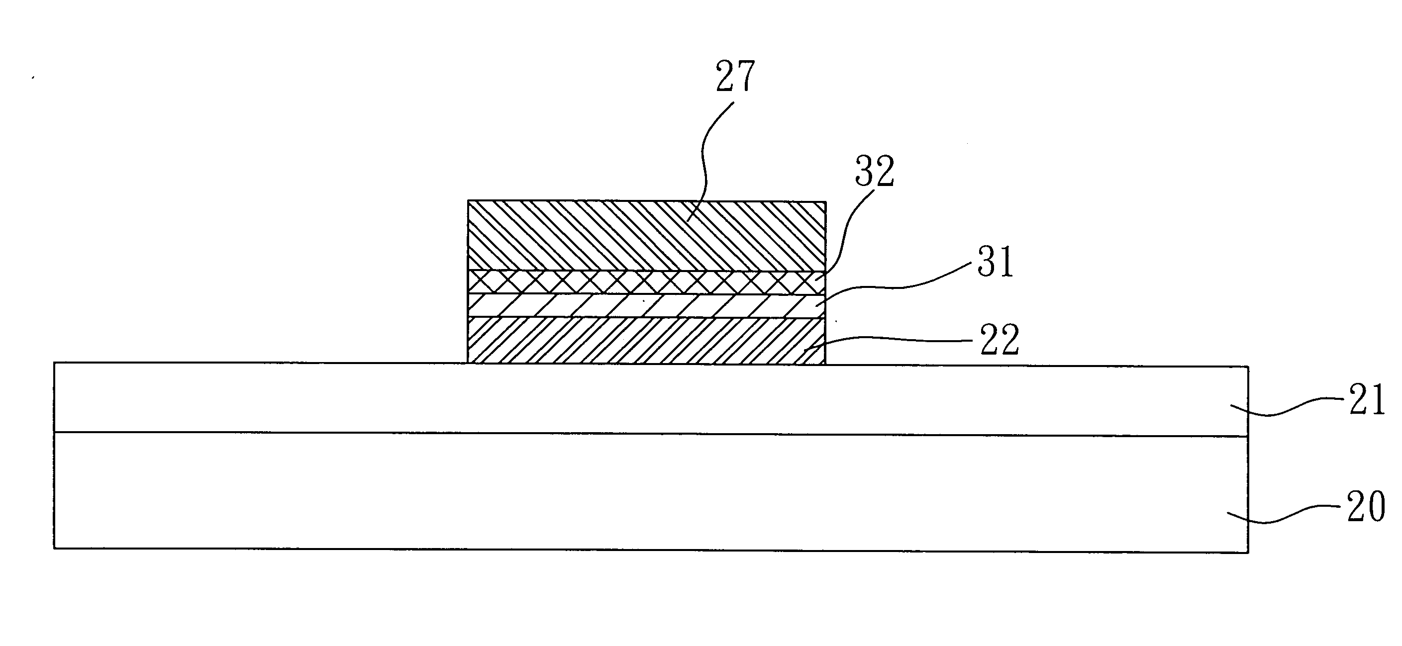
[0024]A conductive adhesion layer is further provided to be sandwiched between the first and the second metal layers to increase the interfacial bonding strength between the first and the second metal layers while forming a new epiwafer and pad construction.
[0025]Furthermore, the roughness of the surface of the electroplated pad is improved by controlling the plating conditions. To obtain finer and more uniform grain size on the pad surface, which subsequently increase the contact surface area between the ball of the gold wire and the pad surface during the wire bonding process, and the bonging strength of the two can be improved thereafter.

Problems solved by technology

However, this mode is found with the following flaws:a. Peel-off between the metal layer 11 and the bond pad; andb. Poor efficiency of the use of precious metal (gold) and comparatively higher production cost incurred from the evaporation process.2. Upon completing the manufacturing process of the metal layer 11, the chipmaker has the process of making the bond pad 12 to be completed by a subcontractor; accordingly, the subcontractor may apply either one of the following processes:a. Complete the bond pad 12 directly on the metal layer 11 in the electroplating process since the electroplating process provides better efficiency than that of evaporation; orb. Complete the photo process and then complete the electroplating process at the designated locations to further improve the utilization efficiency of the gold.
In either process of 2-a or 2-b, however, the peel-off problem resulted from poor adhesion between the metal layer 11 and the bond pad 12 still occur occasionally.
But the higher bonding force could easily damage the structure underneath the pads because of the fragile nature of the LED material.

Method used


Image

  • LED epiwafer pad manufacturing process & new construction thereof
  • LED epiwafer pad manufacturing process & new construction thereof
  • LED epiwafer pad manufacturing process & new construction thereof

Examples


Embodiment Construction

[0040]It is to be noted that in the specification, similar elements are assigned with same number.

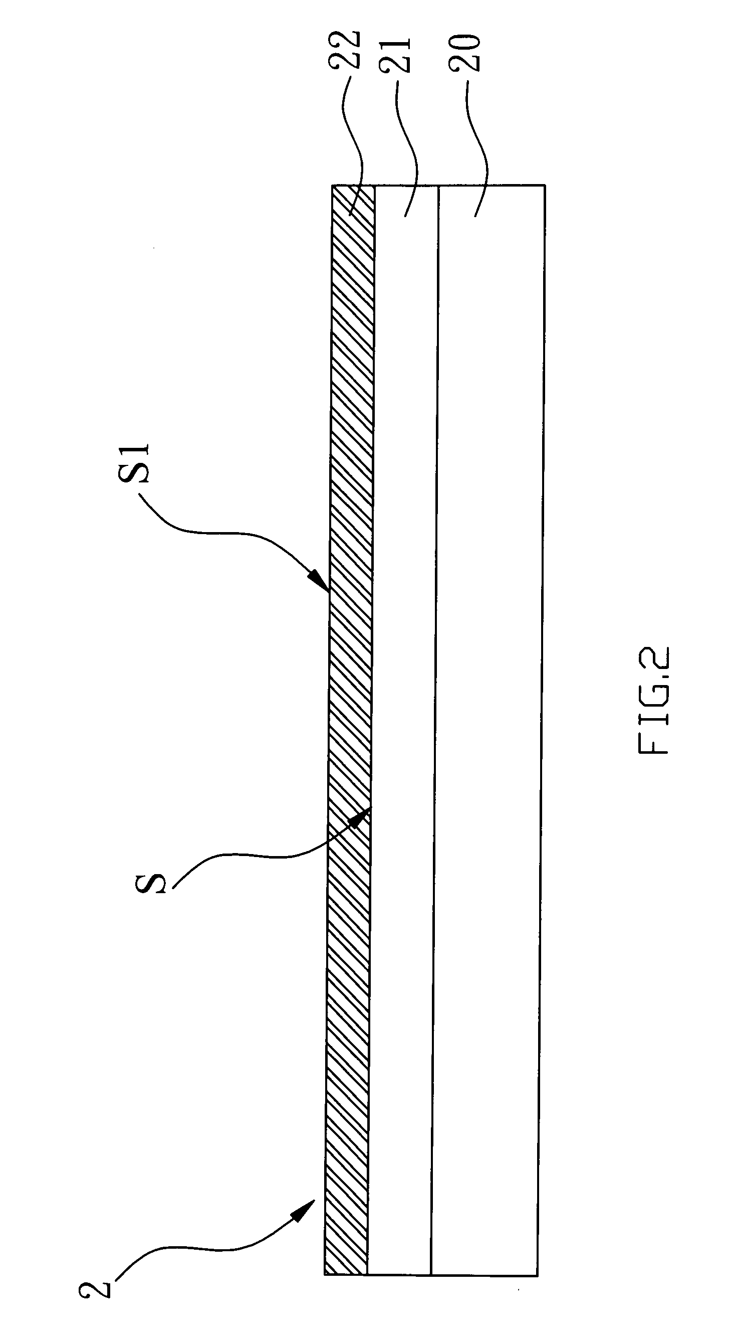
[0041]Referring to FIG. 2 for a first preferred embodiment of the present invention related to a manufacturing process of pad applied in an epiwafer LED; an epiwafer 2 including a substrate 20, an epitaxial layer 21 formed on the substrate 20, and a first metal layer 22 formed on a surface S of the epitaxial layer 21 is prepared.

[0042]Whereas organic contaminants may be attached to the surface of the first metal layer 22 during its transportation, storage in and leaving warehouse, a cleaning process is needed. To clean the first metal layer 22, a first surface S1 of the first metal layer 22 is first processed with a means to increase its interfacial bonding strength to increase its interfacial bonding strength needed in a subsequent wire bonding process. The means to increase the interfacial bonding strength relates to one to clean the surface in physical way (e.g., processed with plasm...


PUM

PropertyMeasurementUnit
temperatureaaaaaaaaaa
interfacial bonding strengthaaaaaaaaaa
surface areaaaaaaaaaaa

Abstract

A pad manufacturing process applied in LED epiwafer and a new construction thereof comprising of a means to increase interfacial bonding strength being provided first to the surface of the epiwafer; followed with a metal deposition means provided to the surface of the epiwafer by having the surface processed with plasma to improve adhesion between pad and epiwafer; and plating conditions being controlled to obtain finer and more uniform grains to correct the problem of pad surface roughness in order to improve the bonding strength between pad and bonding wire. Furthermore, a new construction of epiwafer and a pad is comprised of an epiwafer containing a substrate, an epitaxial layer, and a first metal layer covering the top of the epitaxial layer; an adhesion layer covering the top of the first metal layer; and a pad covering the top of the adhesion layer in sequence.

Description

BACKGROUND OF THE INVENTION[0001](a) Field of the Invention[0002]The present invention is related to a semiconductor manufacturing process and a new construction thereof, and more particularly, to one that is applied in the pad manufacturing process of LED epiwafer and a new construction thereof.[0003](b) Description of the Prior Art[0004]As illustrated in FIG. 1 of the accompanying drawings, a pad 12 in a given thickness using a semiconductor manufacturing process is deposited to a metal layer 11 serving as an electrode in an LED epiwafer 10 of the prior art to prevent destruction of construction and affected electricity due to significant impacts against the epiwafer 10 as a wire 13 is bonded to the pad 12 during wire bonding.[0005]The production modes of the LED electronic industry today feature that:[0006]1. The evaporation process is followed the completion of the metal layer 11 in the same fab by the chipmaker to complete the bond pad 12. However, this mode is found with the f...

Claims


Application Information

Patent Timeline
Patent Type & Authority Applications(United States)
IPC IPC(8): H01L21/44
CPCH01L24/02H01L24/48H01L33/0095H01L33/36H01L33/40H01L33/62H01L2224/48463H01L2924/01078H01L2924/01079H01L2924/00014H01L2224/45144H01L2924/00H01L24/03H01L24/05H01L24/45H01L2224/04042H01L2924/00015H01L2224/05599
Inventor LUH, SONG- PINGHWA, CHIANG JUNGLEE, MING- SHUN
Owner FUPO ELECTRONICS CORP
Learn More