Apparatus for suturing a blood vessel

a technology for sutures and blood vessels, applied in wound clamps, medical science, surgery, etc., can solve the problems of presenting a danger to patients, remaining difficult to use, and inability to accomplish the desired task

Inactive Publication Date: 2006-05-09
GREEN DAVID T
View PDF29 Cites 76 Cited by
  • Summary
  • Abstract
  • Description
  • Claims
  • Application Information

AI Technical Summary

Benefits of technology

[0015]In addition, the device includes a vascular dilator having an elongated body portion disposed within the inner tubular member and a tapered distal tip portion dimensioned to extend beyond the distal end of the inner tubular member for introducing the suturing device into a blood vessel. The vascular dilator is fixedly secured to the inner tubular member of the suturing device by way of a lock, pin, glue or other similar means, and may have a central lumen extending therethrough to accommodate a guidewire. An annular groove is formed between the tapered distal tip portion of the dilator and the elongated body portion of the dilator. This groove will provide a tactile indication to a surgeon as the wall of the blood vessel engages the groove when the device has reached its operating position.
[0016]Preferably, one or more elongated grooves are formed in an exterior surface of the elongated body of the vascular dilator for directing blood flow from the distal tip portion of the dilator to a location remote from the blood vessel for observation. This feature allows the surgeon or an assisting observer to determine whether the device is properly positioned for operation. The grooves direct blood flow to observation ports formed in the tubular body portion of the suturing device, or to a proximal end of the suturing device.

Problems solved by technology

This technique is time consuming, uncomfortable and can cause thrombosis, thereby presenting a danger to the patient.
While these instruments provide improvements over common compression techniques, they remain difficult to use and unable to accomplish the desired task within a relatively short amount of time.

Method used


Image

  • Apparatus for suturing a blood vessel
  • Apparatus for suturing a blood vessel
  • Apparatus for suturing a blood vessel

Examples


Embodiment Construction

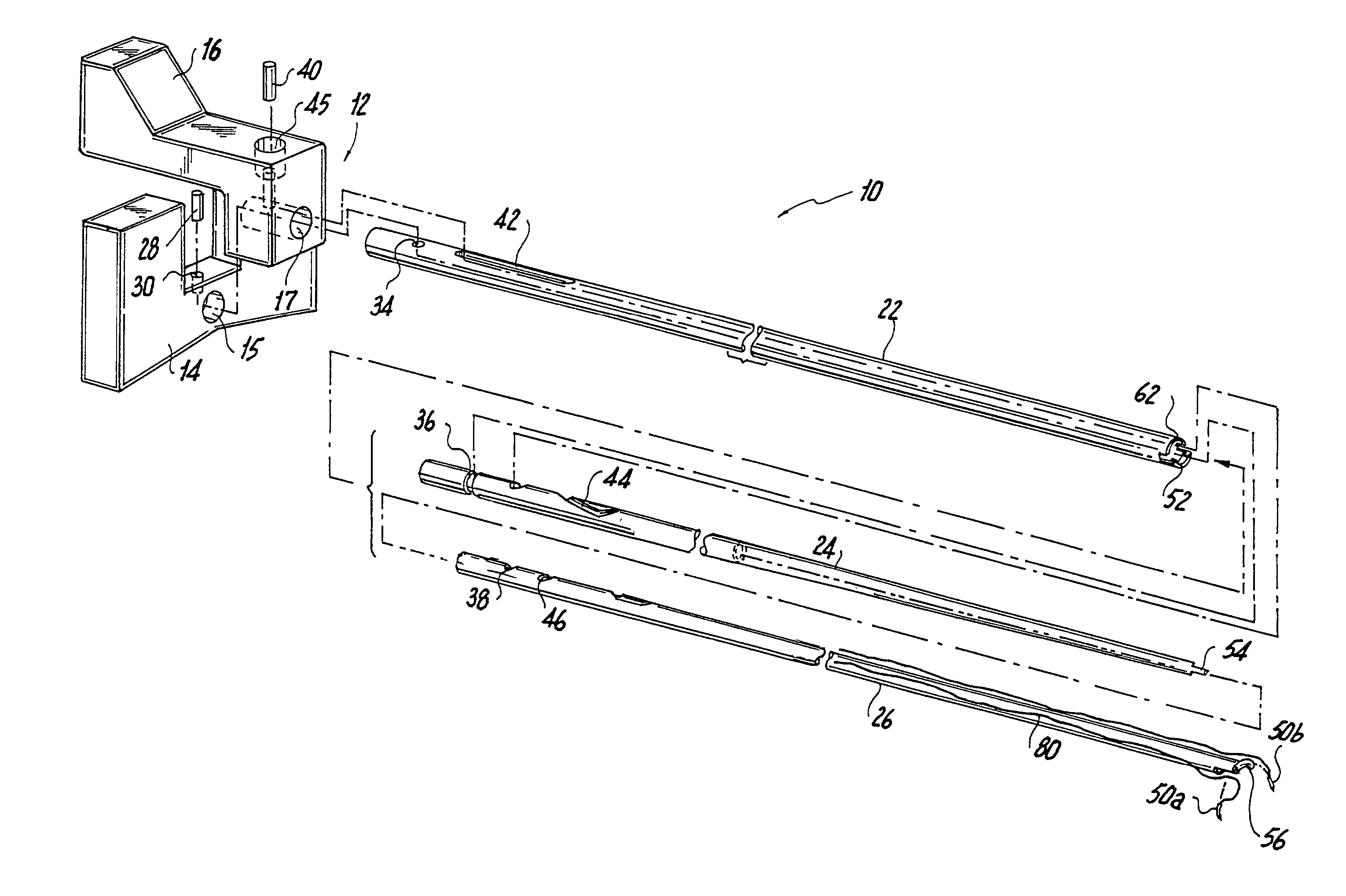
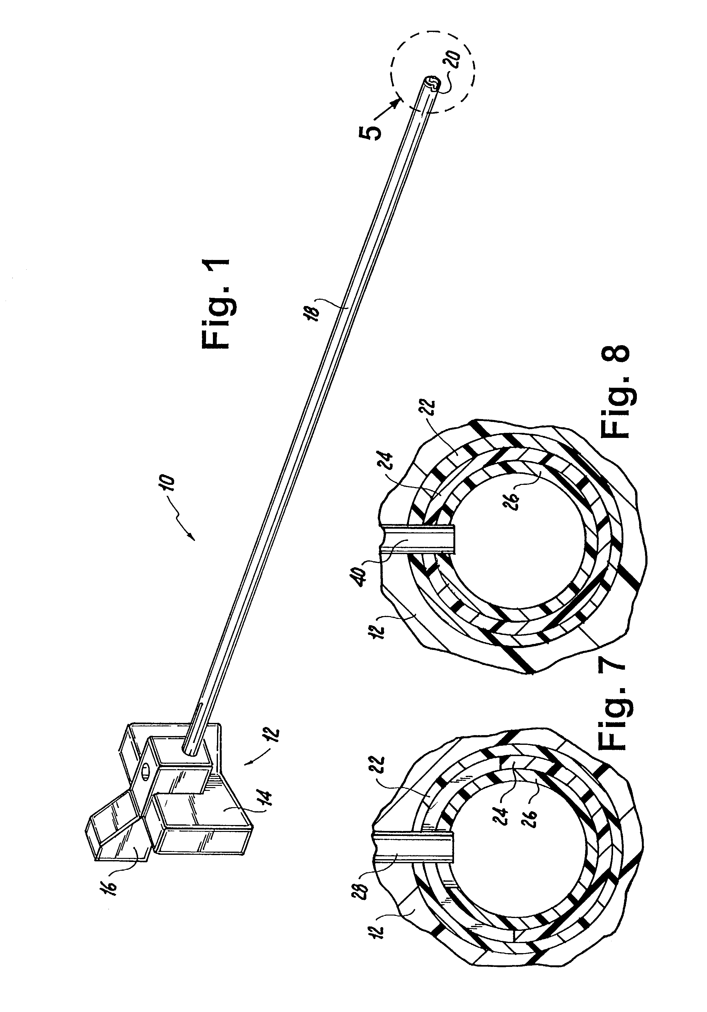
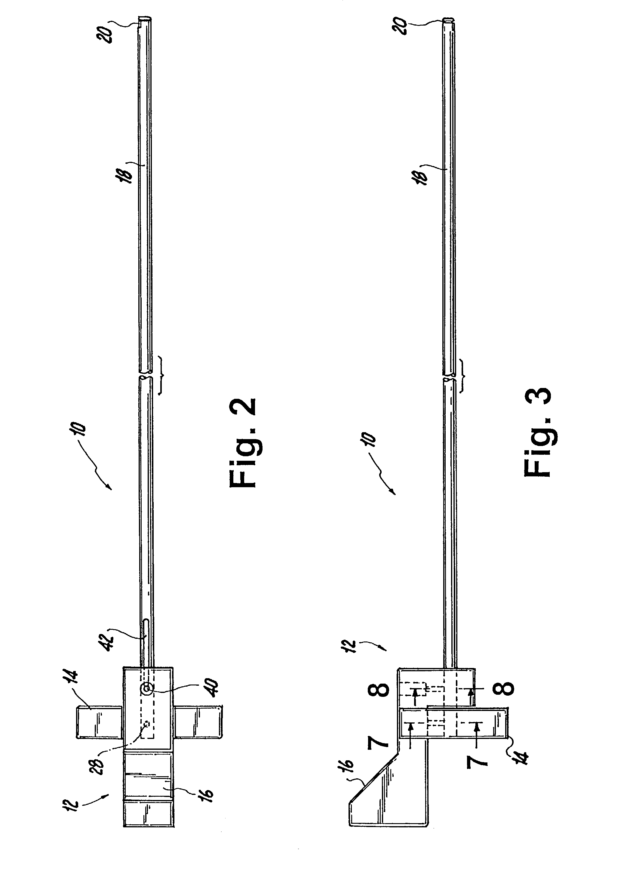
[0065]Referring now to the drawings wherein like reference numerals identify similar structural elements of the apparatus disclosed herein, there is illustrated in FIG. 1 a vascular suturing device constructed in accordance with a preferred embodiment of the subject invention and designated generally by reference numeral 10. In the specification that follows the term “distal” shall refer to the end of the vascular suturing device that is nearest to the surgical site, while the term “proximal” shall refer to the end of the vascular suturing device that is farthest from the surgical site.

[0066]Referring now to FIGS. 1–3, 7 and 8, vascular suturing device 10 includes a proximal handle portion 12 having a stationary support portion 14 and a translating actuation portion 16. The components of handle portion 12 are preferably formed from a high strength thermoplastic material such as, for example, Lexan®. Support portion 14 is ergonomically configured to be positioned on a patient's leg d...


PUM


Abstract

A vascular suturing device is disclosed which includes an elongated tubular body defining opposed proximal and distal end portions and having a longitudinal axis extending therethrough, the body including an inner tubular member, an outer tubular member and a central tubular member disposed between the inner and outer tubular members. The inner tubular member and the central tubular member are mounted for movement relative to the outer tubular member about the longitudinal axis of the body for sequentially driving a pair of suture needles through the wall of a blood vessel to close an incision formed therein. A vascular dilator having a tapered distal tip portion is supported within the inner tubular member and is dimensioned to extend beyond the distal end of the inner tubular member for positioning the suturing device at the incision in the wall of the blood vessel. The dilator is configured to direct blood flow from the distal portion of the dilator to a location remote from the blood vessel for observation to confirm the location of the device.

Description

CROSS-REFERENCE TO RELATED APPLICATIONS[0001]The subject application is a continuation-in-part of U.S. patent application Ser. No. 09 / 794,553 filed Feb. 27, 2001 now U.S. Pat. No. 6,454,777.BACKGROUND OF THE INVENTION[0002]1. Field of the Invention[0003]The subject invention is directed to an apparatus and method for closing incisions in blood vessels, and more particularly, to an apparatus and method for percutaneously applying a suture to the wall of a blood vessel to close a surgical incision formed therein.[0004]2. Background of the Related Art[0005]Surgical procedures requiring the introduction of a catheter into a blood vessel, such as the femoral or iliac artery, are well known in the art. Such procedures involve piercing the wall of the blood vessel, inserting an introducer sheath into the opening in the blood vessel, and maneuvering the catheter through the sheath to a target site within the blood vessel. At the conclusion of the procedure, it is necessary to seal the punct...

Claims


Application Information

Patent Timeline
Patent Type & Authority Patents(United States)
IPC IPC(8): A61B17/08A61D1/00A61B17/00A61B17/04A61B17/06
CPCA61B17/0057A61B17/0469A61B17/0482A61B2017/0038A61B2017/06076A61B2017/00663A61B2017/0472A61B2017/06057A61B2017/00637
Inventor GREEN, DAVID T.
Owner GREEN DAVID T
Why Eureka
Try Eureka