
System and method for monitoring the performance of dense wavelength division multiplexing optical communications systems

a technology of optical communication system and dense wavelength division, applied in the field of optical monitoring, can solve the problem that none of the aforementioned conventional systems is suitable, and achieve the effect of high resolution

Inactive Publication Date: 2006-05-09
THORLABS INC
View PDF25 Cites 4 Cited by
  • Summary
  • Abstract
  • Description
  • Claims
  • Application Information

AI Technical Summary

Problems solved by technology

None of the aforementioned conventional systems is suitable to satisfy the high demands made on a monitoring module for a DWDM system in terms of resolution, measuring accuracy, ASE measurement and dynamic ratio, at the same time and in a suitable manner and to satisfy moreover the demands in terms of short measuring intervals, longevity and low space requirements as well as low-cost realization.

Method used


Image

  • System and method for monitoring the performance of dense wavelength division multiplexing optical communications systems
  • System and method for monitoring the performance of dense wavelength division multiplexing optical communications systems
  • System and method for monitoring the performance of dense wavelength division multiplexing optical communications systems

Examples


Embodiment Construction

Variant 1

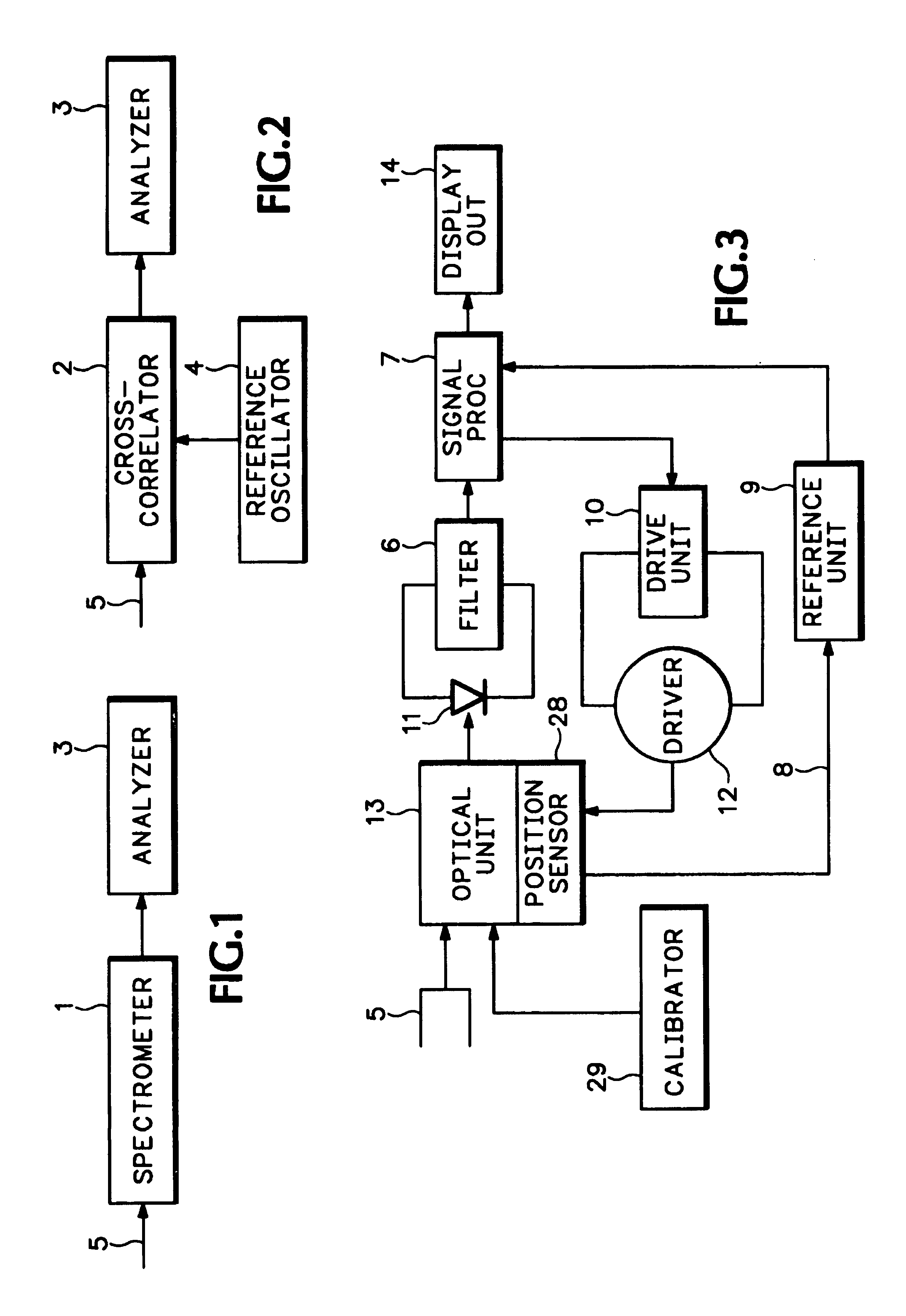
[0029]FIG. 1 illustrates the fundamental structure of the embodiment including a fiber input 5, a narrow-band tunable band-pass filter 1 and an analyzer 3.

[0030]High-resolution spectrometers generally require several dispersive and imaging elements and are adjusted to the wave length to be detected in a complex manner.

[0031]An example of a system based on a multiple spectrograph is illustrated in FIG. 3. The measuring light arrives through a fiber optical waveguide 5 into the optical unit 13 including the spectrometer. The light selected by a particular wave length arrives from the optical unit 13 on the photo detector 11. The electrical signal obtained from the measuring light in the photo detector is passed via a low-pass filter 6 to the signal processor 7. There the wave length is assigned which the reference unit 9 has determined from the position signal 8 of the position sensor 28 and which arrives at the signal processor 7, too. That processor generates also the neces...


PUM


Abstract

A system and method for monitoring all the characteristic parameters of a DWDM communication system is implemented with two variants. Firstly, this is achieved by means of a specific grating spectrometer displaying a high resolution and a high-speed sampling of the measured values, and secondly by the application of an opto-electronic cross correlator as a purely electronic solution. The grating spectrometer is expediently a particular system in a mixed array according to Ebert and Fastie, wherein the light to be measured passes four times through the grating in a specific manner. The opto-electronic cross correlator can mix the working light with a reference light tunable in terms of its frequency to form an electrical low-frequency signal that is analyzed in a high-impedance operation.

Description

RELATED APPLICATION[0001]This application claims benefit of International Aplication No. PCT / EP99 / 097340, filed Oct. 5, 1990 having a priority date of Oct. 5, 1998 based on DE 198 45 701.4. This application has not been published in English.BACKGROUND OF THE INVENTION[0002]The present invention relates to optical monitoring, and more particularly to a system and method of monitoring the performance of dense wavelength division multiplexing optical communication services.[0003]In densely packed WDM systems (dense WDM, DWDM) messages are communicated by light signals at different wave lengths via a single fiber only. Each wave length is the carrier of an information signal. All channels are within the wave length range from presently roughly 1,520 nm to 1,565 nm. The inter-channel separation amounts to a few nanometers or some hundreds of picometers, respectively. For standardization of these telecommunication systems, the international ITU-T Working Group has recommended the wave len...

Claims


Application Information

Patent Timeline
Patent Type & Authority Patents(United States)
IPC IPC(8): H01J40/14G01J3/18G02B6/293G02B6/34H04B10/077H04B10/079H04B10/08H04B10/145H04J14/02
CPCH04J14/02G02B6/4215H04B10/077H04B10/07955G02B6/2931G02B6/29314G02B6/29361G02B6/29385
Inventor PALME, DIETERBANDEMER, ADALBERT
Owner THORLABS INC
Learn More