Permanent magnet rotor construction wherein relative movement between components is prevented

a permanent magnet rotor and rotor construction technology, applied in the direction of dynamo-electric machines, magnetic circuit rotating parts, magnetic circuit shape/form/construction, etc., can solve the problems of preventing their widespread use, not robust and cost-effective rotor construction for the specific system in which the rotor construction is utilized, and not being robust and cost-effectiv

Active Publication Date: 2006-05-09
CALNETIX TECH
View PDF7 Cites 61 Cited by
  • Summary
  • Abstract
  • Description
  • Claims
  • Application Information

AI Technical Summary

Benefits of technology

[0005]The present invention provides an improved construction method and arrangement for a permanent magnet rotor for use in high-speed generators and motors. The construction utilizes a central rod through the core of the rotor that is screwed into end stubs at each end beyond the centrally located permanent magnet section. The permanent magnet section consists of aligned magnet segments forming a hollow rod that has a central hole throughout its length. A thin rod of steel is located in this central hole to support the permanent magnets from within the rod can be fabricated from magnetic or non-magnetic material. At each end of the rod are located threaded sections for attachment to each supporting end stub. These are aligned with the central magnet section with pilot surfaces on each of the rotor and corresponding pilot bores on each stub shaft end. A high strength non-magnetic steel sleeve is interference fit over both the magnets and the end stubs to provide a mechanical link from stub to stub, and provide the necessary rotor stiffness for dynamic performance. The guide rod is used to provide support for the end stubs and central magnet during the grinding and sleeving process. The addition of the pilot surfaces and its close fit with the magnet inner diameter for magnet support are enabling features for a consistently performing rotor assembly in high speed equipment. The rotor is tightly constructed preventing relative motion between the rotor components and thus maintains its structural integrity throughout its operating life.
[0006]The use of a central rod is accordance with the teachings of the present invention thus significantly improves the manufacturability and reliability of the rotor while reducing rotor cost and simplifying the rotor construction.

Problems solved by technology

Although the designs set forth in the referenced patents provide advantages over the prior art systems described therein, the rotor construction described are not robust and cost effective for the specific system that the rotor construction is utilized with.
In addition, difficulties in the prior art with magnets breaking, shifting, collapsing during assembly, and releasing from the rotor during operation have prevented their widespread use.

Method used


Image

  • Permanent magnet rotor construction wherein relative movement between components is prevented
  • Permanent magnet rotor construction wherein relative movement between components is prevented
  • Permanent magnet rotor construction wherein relative movement between components is prevented

Examples


Embodiment Construction

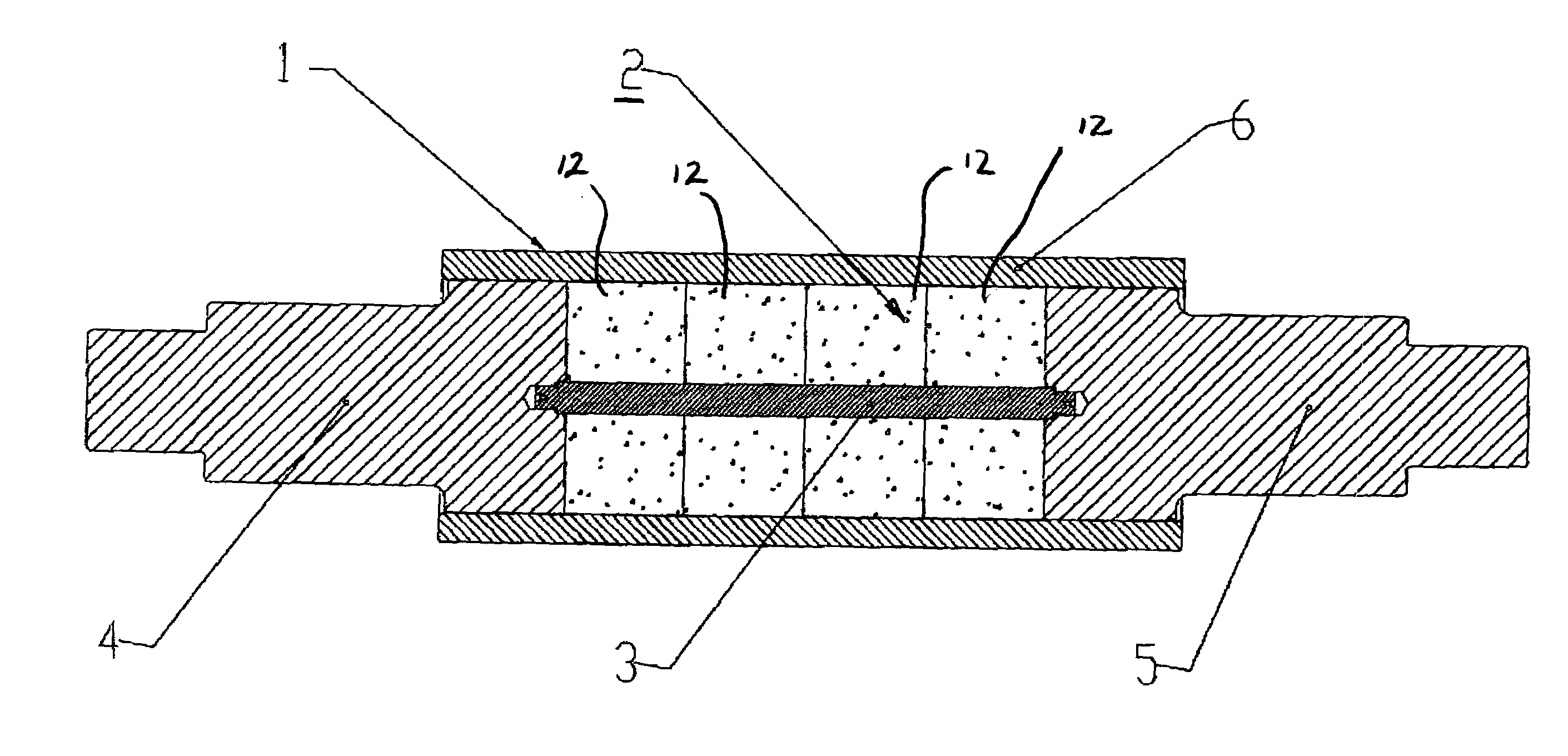
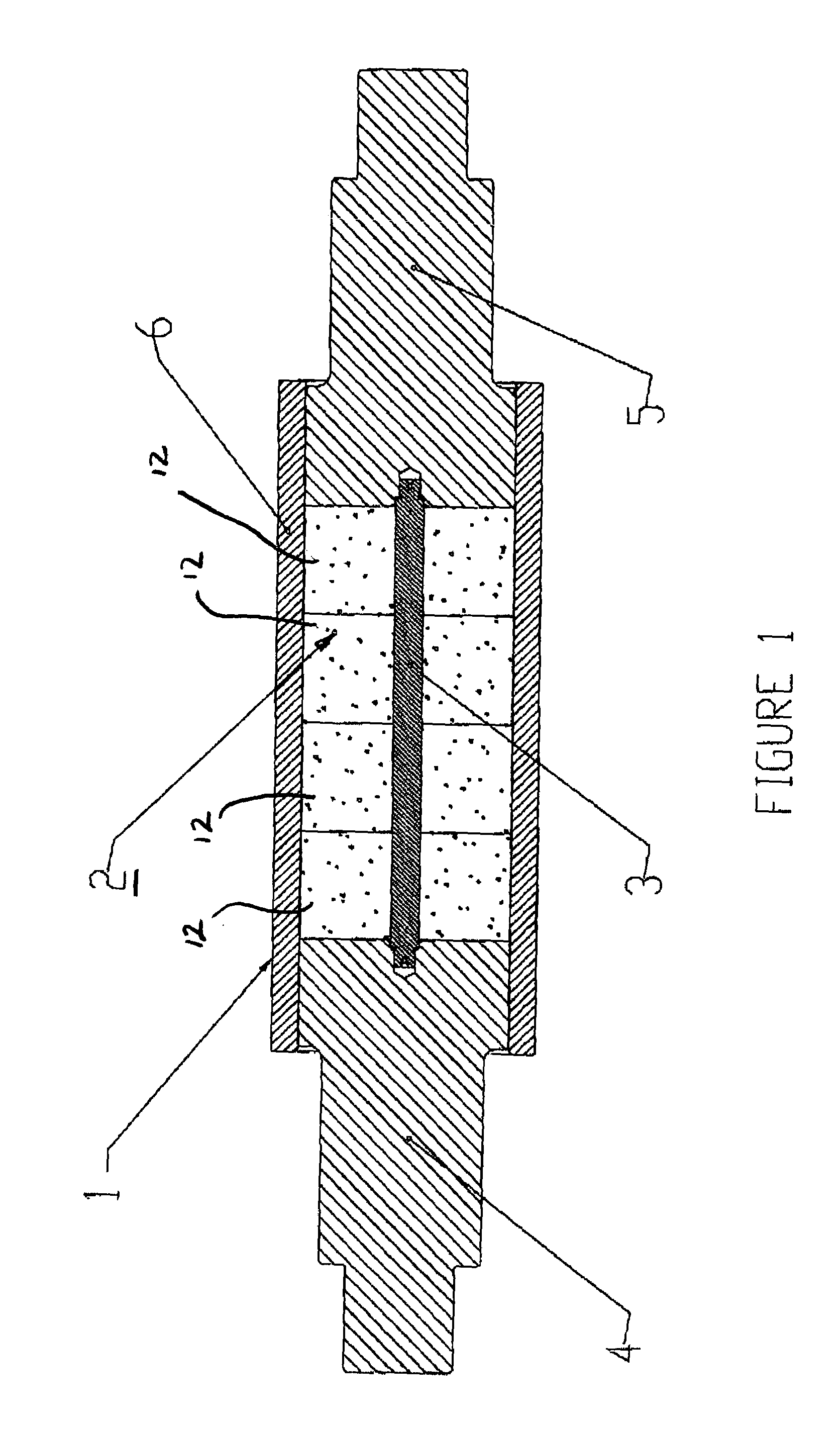
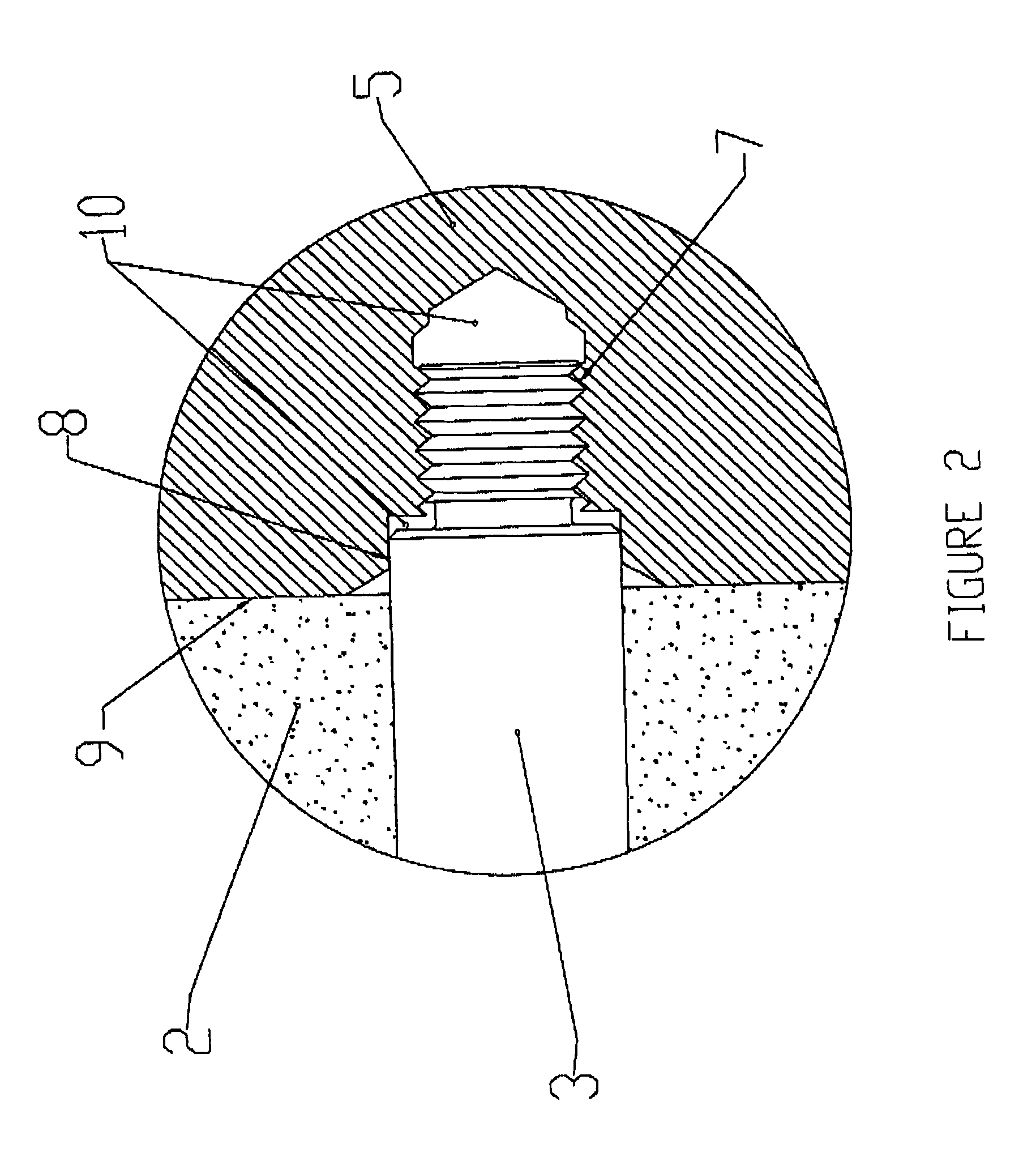
[0010]FIG. 1 is a sectional view of the assembled rotor 1 in accordance with the teachings of the present invention. Rotor assembly 1 comprises permanent magnet 2, guide rod 3 and end stub shafts, or end pieces, 4 and 5. Permanent magnet 2 is formed with one or multiple segments bonded together to form an opening adapted to receive guide rod 3 therethrough. This type of rotor if typically used on a high speed, two pole permanent magnet motor and / or generator. The permanent magnet is magnetized to its desired magnetic field either at the component, sub assembly, or final assembly level. Magnetizing at the final assembly level allows the rotor to be first assembled and machined, thereby reducing cost and complexity.

[0011]The specific features of a rotor using segmented permanent magnets is disclosed in copending application Ser. No. 10 / 078,572, filed Feb. 10, 2002, the details of which are necessary for an understanding of the present invention being incorporated herein by reference. ...


PUM


Abstract

A rotor construction may comprise a rotor with a centrally located permanent magnet section having aligned magnet segments and having a central hole throughout its length. A thin rod of magnetic steel is located in this central hole to support the permanent magnets from within. At each end of the rod are located threaded sections for attachment to supporting end stubs. A high strength steel sleeve is interference fit over both the magnets and the end stubs to provide a mechanical link from stub to stub. The guide rod insures that the end stubs and central magnet are concentric during initial processing, prevents relative motion between the rotor components and provides support for the magnet once the sleeve is installed.

Description

BACKGROUND OF THE INVENTION[0001]1. Field of the Invention[0002]The present invention provides a high stiffness permanent magnet rotor for use in high speed electric motors and generators.[0003]2. Description of the Prior Art[0004]The apparatus set forth in U.S. Pat. Nos. 4,667,123 and 4,741,094 utilize sleeved magnet rotors that offer containment of permanent magnet rotors at high speeds. Although the designs set forth in the referenced patents provide advantages over the prior art systems described therein, the rotor construction described are not robust and cost effective for the specific system that the rotor construction is utilized with. In addition, difficulties in the prior art with magnets breaking, shifting, collapsing during assembly, and releasing from the rotor during operation have prevented their widespread use. What is thus desired is to provide a cost effective method to assemble, align and lock the permanent magnets into the rotor allowing for high speed, high stre...

Claims


Application Information

Patent Timeline
Patent Type & Authority Patents(United States)
IPC IPC(8): H02K41/00H02K1/27H02K21/12
CPCH02K1/2733
Inventor MCMULLEN, PATRICK T.HUYNH
Owner CALNETIX TECH
Why Eureka
Try Eureka