
Electric power steering apparatus

a technology of electric power steering and electric motor, which is applied in the direction of non-deflectable wheel steering, underwater vessels, special data processing applications, etc., can solve the problems of increasing the cost of the apparatus, and the driver being subject to an incongruous feeling, so as to reduce the incongruous steering feeling, reduce the cost of construction, and reduce the error margin of the two signals

Active Publication Date: 2006-05-09
HONDA MOTOR CO LTD
View PDF28 Cites 2 Cited by
  • Summary
  • Abstract
  • Description
  • Claims
  • Application Information

AI Technical Summary

Benefits of technology

[0011]Because the angular position of the brushless motor is obtained by control means consisting of a microcomputer on the basis of a table stored in ROM provided in the control means, there is unlikely to be any affect of noise, there is less possibility of calculation being interrupted, and incongruous steering feelings can be reduced. Because an RD convertor part is unnecessary, the construction can be made cheaper than in related art.
[0012]Preferably, an electric power steering apparatus according to the invention further includes second control means additional to the first control means, the second control means performs the same angular position calculation as the first control means, and any abnormality is detected by a value calculated by the first control means and a value calculated by the second control means being compared. In this case, because the output difference between the first control means and the second control means is extremely small, and the margin for error of the two signals can be made small, the precision of abnormality detection increases.
[0013]Also, in an electric power steering apparatus according to the invention further including second control means additional to the first control means, the second control means performing the same angular position calculation as the first control means, the first control means and the second control means may preferably have direction prohibiting means for restricting rotation of the brushless motor on the basis of a steering input of a driver. In this case, even when one of the first control means and the second control means has become abnormal, it is possible for certain direction prohibition to be carried out by the other. Also, a circuit for detecting abnormality of the first control means and the second control means becomes unnecessary, and a simple circuit construction can be adopted.
[0014]Also, in this invention, preferably, the angular position detecting means is a resolver, there are further provided sample-hold circuits for sample-holding outputs from the resolver, and the first control means or the second control means outputs a reference clock pulse to the resolver and a sample-hold timing pulse to the sample-hold circuits. In this case, it is possible to output a sample-hold timing correctly synchronized with the peaks of an excitation signal. Also, the timing can be changed freely with the sample-hold timing remaining synchronized correctly with the peaks of the excitation signal.

Problems solved by technology

When an RD convertor part for obtaining the angular position of a rotor on the basis of output signals from a resolver like this is employed in an electric power steering apparatus, there has been the problem that the RD convertor part is expensive and raises the cost of the apparatus.
Also, when the RD convertor is performing angle calculation with an extremely short period and for example spike noise intrudes, because the computation itself is reset (computation is interrupted) there is a possibility of the driver being subjected to an incongruous feeling.

Method used


Image

  • Electric power steering apparatus
  • Electric power steering apparatus
  • Electric power steering apparatus

Examples


Embodiment Construction

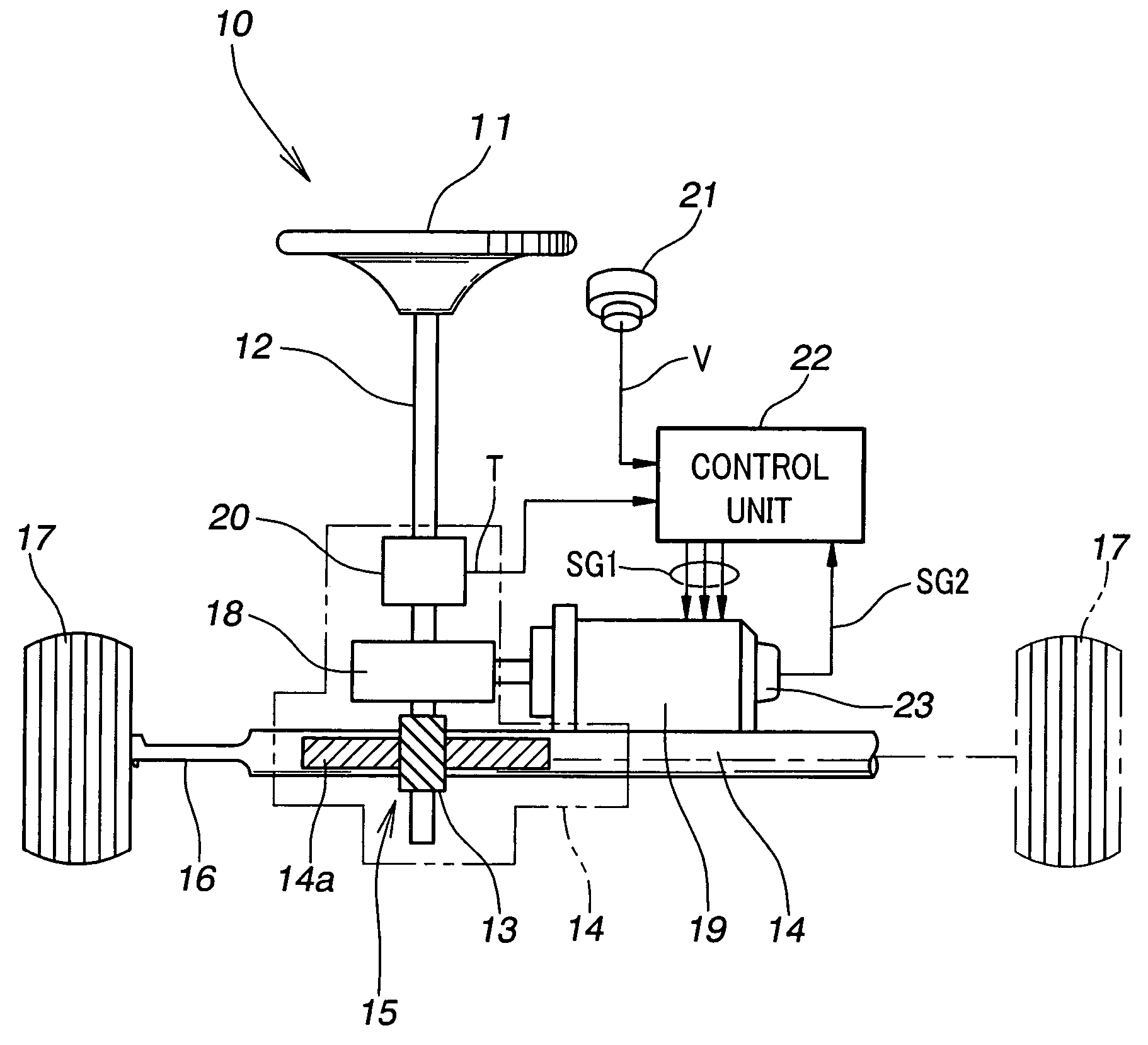
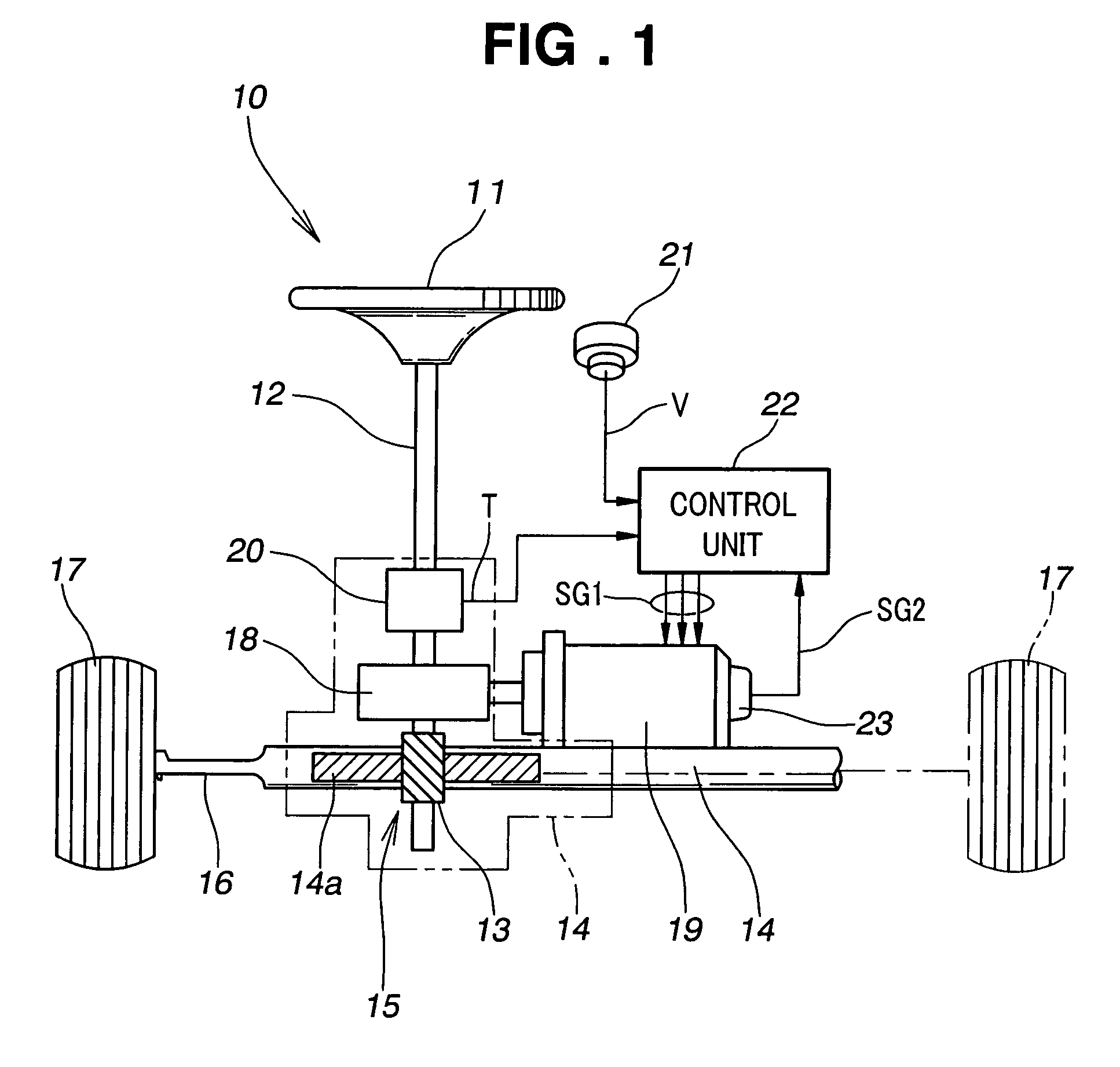
[0027]The overall construction of an electric power steering apparatus according to the invention will be described on the basis of FIG. 1 through FIG. 4. An electric power steering apparatus 10 shown in FIG. 1 is constructed to apply an assisting steering force (steering torque) to a steering shaft 12 connected to a steering wheel 11.

[0028]A top end of the steering shaft 12 is connected to the steering wheel 11, and a bottom end is connected to a pinion gear 13. The pinion gear 13 is connected to a rack shaft 14 having a rack gear 14a for meshing with the pinion gear 13. The pinion gear 13 and the rack gear 14a constitute a rack and pinion mechanism 15. Front wheels 17, 17 are connected to the ends of the rack shaft 14 by tie rods 16, 16.

[0029]A power transmitting mechanism 18 is mounted on the steering shaft 12, and the power transmitting mechanism 18 is connected to a brushless motor 19.

[0030]The brushless motor 19 outputs a turning force (torque) for supplementing the steering t...


PUM


Abstract

An electric power steering apparatus using a brushless motor is disclosed. The electric power steering apparatus has a microcomputer for calculating a target current to the brushless motor on the basis of a torque signal outputted from a steering torque detecting part. The microcomputer has a table stored in ROM. The microcomputer calculates the angular position of the brushless motor by referring to the table on the basis of a signal outputted by a resolver.

Description

FIELD OF THE INVENTION[0001]This invention relates to an electric power steering apparatus for applying force from an electric motor to a steering mechanism to lighten the steering force needed from a driver.BACKGROUND OF THE INVENTION[0002]An electric power steering apparatus reduces the steering force needed from a driver by drive-controlling an electric motor with a motor drive control part on the basis of a steering torque signal outputted by a steering torque detecting part and a vehicle speed signal outputted by a vehicle speed detecting part. Electric power steering apparatuses that use a brushless motor as the electric motor are known.[0003]With an electric power steering apparatus that uses a brushless motor, because there is no dropping or fluctuation of motor output due to a voltage drop between brushes and a commutator, it is possible to obtain a stable auxiliary steering force. Because the inertia moment of the motor is small compared to that of a motor with brushes, a ...

Claims


Application Information

Patent Timeline
Patent Type & Authority Patents(United States)
IPC IPC(8): H02P7/00B62D6/00B62D5/04B62D101/00B62D113/00B62D119/00B62D137/00
CPCB62D5/046B62D5/0493B62D5/0487B62D5/0463
Inventor MUKAI, YOSHINOBUNAKANO, YASUHIROTAKAGI, MASANORIHORII, HIROAKITSURUMIYA, OSAMUMORISHITA, FUMIHIROKURIBAYASHI, TAKASHI
Owner HONDA MOTOR CO LTD
Learn More