Ultra wideband internal antenna

a wideband, internal antenna technology, applied in the direction of resonant antennas, elongated active element feeds, radiating element structural forms, etc., can solve the problems of difficult to design the external shape of helical antennas to provide attractive and portable terminals, body, and sar characteristics of absorption rate (sar), and achieve the effect of easy miniaturization

Inactive Publication Date: 2006-05-09
SAMSUNG ELECTRO MECHANICS CO LTD
View PDF3 Cites 21 Cited by
  • Summary
  • Abstract
  • Description
  • Claims
  • Application Information

AI Technical Summary

Benefits of technology

[0015]Another object of the present invention is to provide an ultra wideband internal antenna, which can be easily miniaturized while being provided in a mobile communication terminal.

Problems solved by technology

Such an antenna is advantageous in that it can obtain a high gain, but disadvantageous in that Specific Absorption Rate (SAR) characteristics, which are the measures of an electromagnetic wave's harm to the human body, are worsened due to the omni-directionality thereof.
Further, since the helical antenna is designed to protrude outward from a terminal, it is difficult to design the external shape of the helical antenna to provide an attractive and portable terminal.
Since the monopole antenna requires a separate space sufficient for the length thereof in a terminal, there is a disadvantage in that product design toward the miniaturization of terminals is hindered.
In such a wideband technology, the development of low power consumption and low cost semiconductor devices, the standardization of Media Access Control (MAC) specifications, the development of actual application layers, and the establishment of evaluation methods in high frequency wideband wireless communication have become major issues.
If the radiation characteristic of an antenna varies according to direction, a problem occurs such that speech quality varies according to the direction the terminal faces.
Further, the antenna is also problematic in that, since the size of the tap 10 emitting radiation is somewhat large, the tap 10 must occupy a large space in a mobile terminal.

Method used


Image

  • Ultra wideband internal antenna
  • Ultra wideband internal antenna
  • Ultra wideband internal antenna

Examples


Embodiment Construction

[0035]Preferred embodiments of the present invention are described with reference to the attached drawings below. Reference now should be made to the drawings, in which the same reference numerals are used throughout the different drawings to designate the same or similar components. In the following description of the present invention, detailed descriptions may be omitted if it is determined that the detailed descriptions of related well-known functions and construction may make the gist of the present invention unclear.

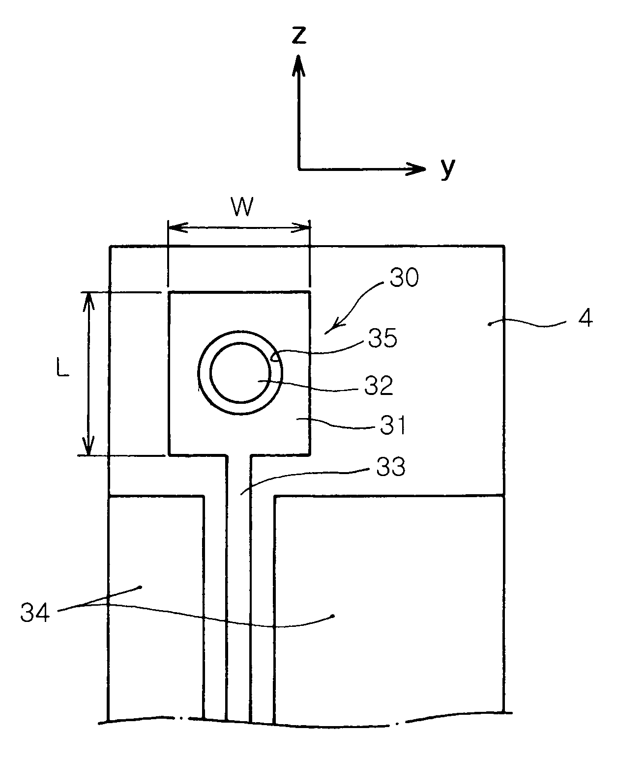
[0036]FIG. 3 is a top view of an ultra wideband internal antenna according to an embodiment of the present invention.

[0037]Referring to FIG. 3, an ultra wideband internal antenna 30 according to an embodiment of the present invention includes first and second radiation parts 31 and 32, a feeding line 33, upper ground parts 34, and lower ground parts (not shown) that are formed on a dielectric substrate 4.

[0038]Preferably, the first radiation part 31 may have an out...


PUM


Abstract

The present invention relates to an ultra wideband (UWB) internal antenna. The ultra wideband internal antenna includes a first radiation part, a feeding line, a second radiation part, and a ground part. The first radiation part is formed on a top surface of a dielectric substrate and provided with an internal slot. The feeding line supplies a current to the first radiation part. The second radiation part is formed in the internal slot of the first radiation part on the top surface of the dielectric substrate, the second radiation part being conductive. The ground part grounds both the first and second radiation parts. The second radiation part determines an ultra wideband by mutual electromagnetic coupling with the first radiation part using a current element induced due to the current supplied to the first radiation part.

Description

RELATED APPLICATION[0001]The present application is based on, and claims priority from, Korean Application Number 2004-0085775, filed Oct. 26, 2004, the disclosure of which is hereby incorporated by reference herein in its entirety.BACKGROUND OF THE INVENTION[0002]1. Field of the Invention[0003]The present invention relates generally to an antenna provided in a mobile communication terminal to transmit and receive radio signals and, more particularly, to an ultra wideband internal antenna, which is provided in a mobile communication terminal and is capable of processing ultra wideband signals.[0004]2. Description of the Related Art[0005]Currently, mobile communication terminals are required to provide various services as well as be miniaturized and lightweight. To meet such requirements, internal circuits and components used in the mobile communication terminals trend not only toward multi-functionality but also toward miniaturization. Such a trend is also applied to an antenna, whi...

Claims


Application Information

Patent Timeline
Patent Type & Authority Patents(United States)
IPC IPC(8): H01Q9/28
CPCH01Q1/243H01Q1/38H01Q5/378H01Q5/25H01Q9/40H01Q13/10
Inventor LEE, JAE CHAN
Owner SAMSUNG ELECTRO MECHANICS CO LTD
Why Eureka
Try Eureka