Radio communication apparatus using adaptive antenna

Inactive Publication Date: 2006-05-09
KK TOSHIBA
View PDF11 Cites 25 Cited by
  • Summary
  • Abstract
  • Description
  • Claims
  • Application Information

AI Technical Summary

Benefits of technology

[0023]In order to solve the above problems, the present invention has the main feature that an arrival angle range indicating an approximate arrival direction of a desired wave is estimated on the basis of a delay profile estimated in a

Problems solved by technology

In land mobile communications, there will frequently occur degradation in received signal level due to fading, or a signal distortion due to co-channel interference (CCI) or intersymbol interference (ISI).
As stated above, although the propagation channel response differs between uplink and downlink, there is reversibility between uplink and downlink with respect to the direction of arrival of radio waves.
However, a great amount of calculations is required for a high-resolution DOA estimation algorithm represented by MUSIC.
This algorithm is not suitable in a case of estimating the DOA which varies from time to time depending on the movement of the terminal station or a variat

Method used


Image

  • Radio communication apparatus using adaptive antenna
  • Radio communication apparatus using adaptive antenna
  • Radio communication apparatus using adaptive antenna

Examples


first embodiment

(First Embodiment)

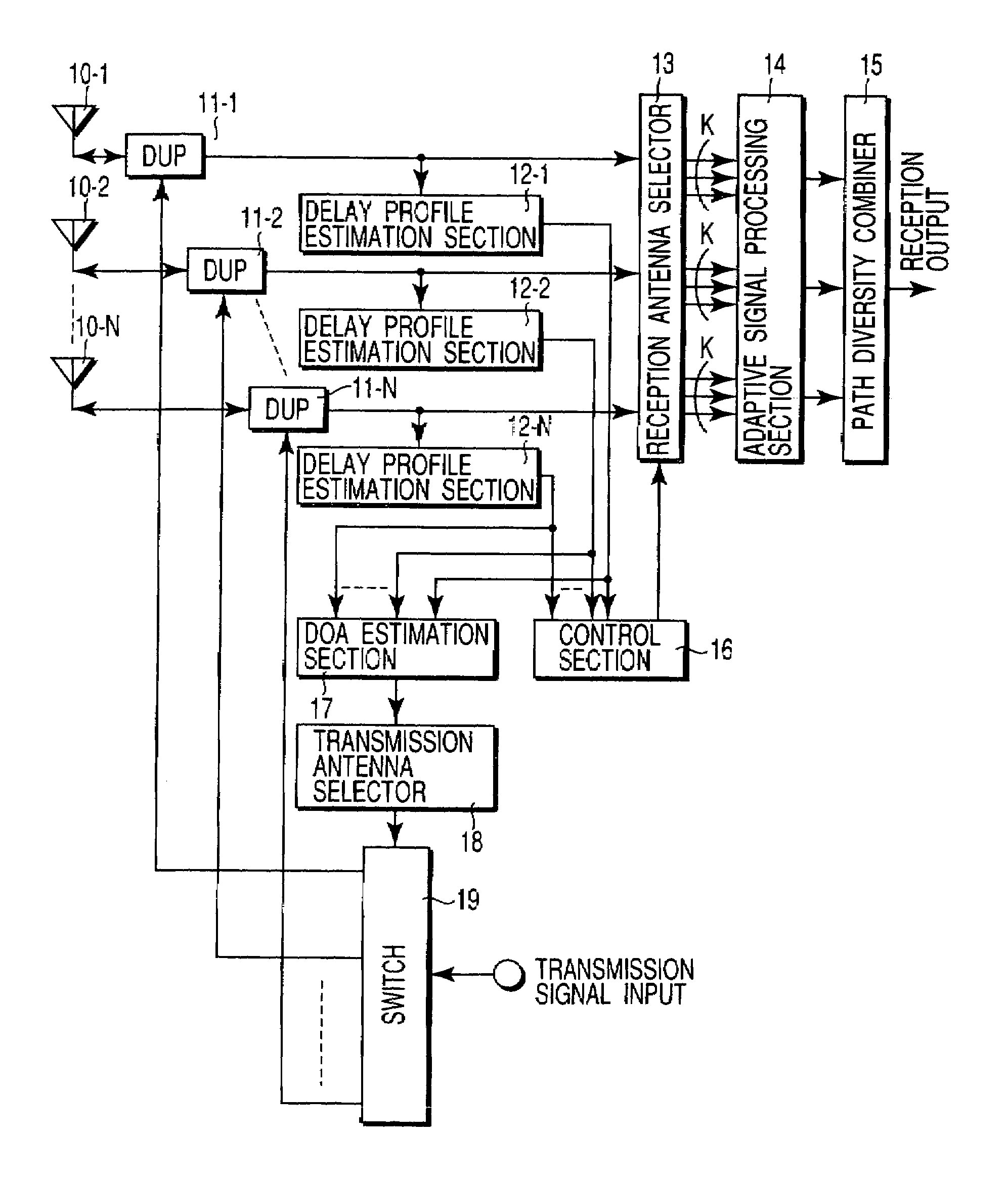
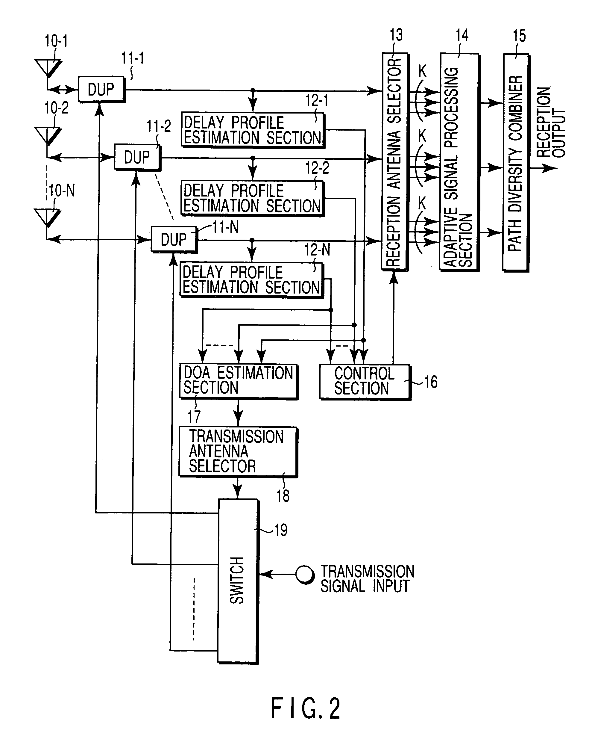
[0049]FIG. 2 is a block diagram showing the structure of a radio communication apparatus according to a first embodiment of the present invention.

[0050]The radio communication apparatus of this embodiment comprises a plurality of antennas 10-1 to 10-N for transmission / reception, which have mutually different directivities; duplexers 11-11 to 11-N for dividing transmission / reception signals having different frequencies; delay profile estimation sections 12-1 to 12-N; a reception antenna selector 13 for selecting a predetermined number of antennas for reception (i.e. reception antennas) from the antennas 10-1 to 10-N; an adaptive signal processing section 14 and a path diversity combiner 15 for subjecting the received signals from the selected reception antennas to a temporal / spatial equalization signal processing; a control section 16 for controlling the reception antenna selector 13; a DOA (Direction of Arrival) estimation section (an arrival angle range estimation...

second embodiment

(Second Embodiment)

[0068]FIG. 4 shows the structure of a radio communication apparatus according to a second embodiment of the invention. The structural elements common to those in FIG. 2 are denoted by like reference numerals, and only differences from the first embodiment will be described.

[0069]In the second embodiment, omni-directional antennas 20-1 to 20-N are substituted for the directional antennas 10-1 to 10-N used in the first embodiment. A beam forming section 21 is connected between the antennas 20-1 to 20-N and the duplexers 11-1 to 11-N. The beam forming section 21 forms a plurality of beams with different directions of radiation (i.e. different directivities), that is, a plurality of directivity patterns. The beam forming section 21 may be realized, for example, by a Butler matrix circuit using analog elements, or a digital circuit performing spatial FFT (Fast Fourier Transform).

[0070]Since the beam forming section 21 is used, the reception antenna selector 13 in FIG. ...

third embodiment

(Third Embodiment)

[0075]FIG. 5 shows the structure of a radio communication apparatus according to a third embodiment of the invention. This embodiment is based on the structure of the first embodiment, and it aims at forming a transmission beam pattern capable of effectively enhancing an average reception SIR at an opposing-side station, or a terminal station.

[0076]The structural elements common to those in FIG. 2 are denoted by like reference numerals, and only differences from the first embodiment will be described. In the third embodiment, a direction of arrival estimation section 27 for estimating a direction of arrival of a desired wave is provided in addition to the arrival angle range estimation section 17 for estimating an arrival angle range of a desired wave in the first and second embodiments. In addition, a transmission weight vector generator 30 is added, and the switch 19 in FIG. 2 is replaced with weighting sections (multipliers) 31-1 to 31-N.

[Re: Reception Operation...


PUM


Abstract

In a radio communication apparatus, delay profiles of a desired wave and delay waves thereof are estimated by plural delay profile estimation sections for each of received signals from directional antennas constituting an array antenna. Received signals from the antennas selected by a reception antenna selector on the basis of the delay profile are subjected to a temporal/spatial equalization processing by an adaptive signal processing section and a path diversity combining section, thereby obtaining a reception output. An arrival angle range of the desired wave is estimated by a DOA estimation section from the delay profile estimated by the delay profile estimation section. Based on the arrival angle range, the antenna for transmission is selected by a transmission antenna selection section, and transmission signals are sent out.

Description

CROSS-REFERENCE TO RELATED APPLICATIONS[0001]This application is a divisional of U.S. app. Ser. No. 09 / 745,475, filed Dec. 26, 2000, now U.S. Pat. No. 6,771,988, which is based upon and claims the benefit of priority from the prior Japanese Patent Applications No. 11-371762, filed Dec. 27, 1999; and No. 2000-351612, filed Nov. 17, 2000, the entire contents of each are incorporated herein by reference.BACKGROUND OF THE INVENTION[0002]The present invention relates generally to a radio communication apparatus using an adaptive antenna, which is applied to a mobile radio communication system, etc., and more particularly to a transmission beam control apparatus for desirably controlling antenna directivity at the time of transmission.[0003]In land mobile communications, there will frequently occur degradation in received signal level due to fading, or a signal distortion due to co-channel interference (CCI) or intersymbol interference (ISI).[0004]In such a severe environment for signal p...

Claims


Application Information

Patent Timeline
IPC IPC(8): H04B1/38H01Q3/24H01Q3/26H01Q21/20H04B7/06H04B7/08H04B7/10H04B7/26H04W16/28H04W28/18H04W88/08
CPCH04B7/086H04B7/0617
Inventor MATSUOKA, HIDEHIROSHOKI, HIROKI
Owner KK TOSHIBA
Why Eureka
Try Eureka