Thermal therapy device and therapy system using the same

a technology of heat therapy and therapy device, which is applied in the direction of contraceptive devices, prostheses, therapy, etc., can solve the problems of difficult for motor impaired patients to accurately position the therapy apparatus on the acupuncture points around the spinal joints, and most patients cannot effectively use the therapy apparatus, so as to facilitate the service of the control box

Active Publication Date: 2006-05-09
MIGUN MEDICAL INSTR
View PDF7 Cites 3 Cited by
  • Summary
  • Abstract
  • Description
  • Claims
  • Application Information

AI Technical Summary

Benefits of technology

[0019]Therefore, the present invention has been created in view of the above problems, and it is an object of the present invention to provide a heat therapy device for a heat therapy system that is configured in such a fashion that it simultaneously applies acupressure and thermal treatment to aching parts of the patient's body and may be effectively used on any regions of the patient's body without restriction, thereby maximizing the healing effect of the system and allowing it to be widely used on the patient's entire body.
[0020]It is another object of the present invention to enable the patient to adjust the strength of acupressure and thermal treatment according to their own particular body shape and aching parts, thereby preventing the deterioration of the thermal treatment effect thereof due to the different body shapes of the patients.
[0022]In accordance with one aspect of the present invention, the above and other objects can be accomplished by the provision of a heat therapy system using heat therapy devices, the heat therapy system comprising: upper and lower bodies; control boxes formed at adjacent portions of the upper and lower bodies and adapted to control their respective components; control panels shaped like a “-shaped” plate and hinged such that each control panel is connected on one side to an upper side of its respective control box through connectors, thereby facilitating service of the control boxes; motors formed at a center position of the lower portions of the upper and lower bodies, respectively; pulleys formed on opposite sides of the motors; upper and lower rails installed between the motors and pulleys and arranged in two rows to correspond to the spine of the body; timing belts positioned along a central axis between the upper and lower rails and directly connected to the motors and pulleys, each timing belt being formed with bosses at its lower surface; upper and lower mobile units coupled with the timing belts and seated on the upper and lower rails, the upper and lower mobile units being formed with a plurality of heat therapy devices; two other heat therapy devices formed on the tipper body, the heat therapy devices being formed on left and right sides of the upper rails and adapted to apply acupressure and thermal treatment to both arms of the patient; and a portable heat therapy device installed to apply acupressure on the front part of the patient lying on his / her back on the heat therapy system for applying acupressure on the body using the heat therapy devices.

Problems solved by technology

Such a therapy method, however, has a problem that it is difficult for motor impaired patients to use the therapy apparatus because the patient has to position the therapy apparatus on the spinal joints by himself / herself, and also move it to the other spinal joints at regular time intervals by himself / herself.
In addition, it is difficult for most patients to accurately position the therapy apparatus on the acupuncture points around the spinal joints.
Consequently, most patients cannot effectively use the therapy apparatus.
The conventional techniques as stated above, however, have problems in that it is impossible to effectively apply the heat therapy device of the heat therapy system to the entire body without restriction, and to simultaneously apply acupressure and thermal treatment to aching parts of the patient's body.
This deteriorates operability and reliability thereof, as well as increasing its manufacturing cost.
The device for vertically operating the heat therapy devices, however, has problems in that it cannot adjust the strength of acupressure and thermal treatment according to the different body shape and aching parts of the patient, and that the heat therapy devices coupled to the carrier provided in a lower mattress cannot move according to the motion of the patient's legs, thereby deteriorating the heat therapy effect.
In addition, in case of the device's failure, the patient has to disassemble the device to repair it.

Method used


Image

  • Thermal therapy device and therapy system using the same
  • Thermal therapy device and therapy system using the same
  • Thermal therapy device and therapy system using the same

Examples


Embodiment Construction

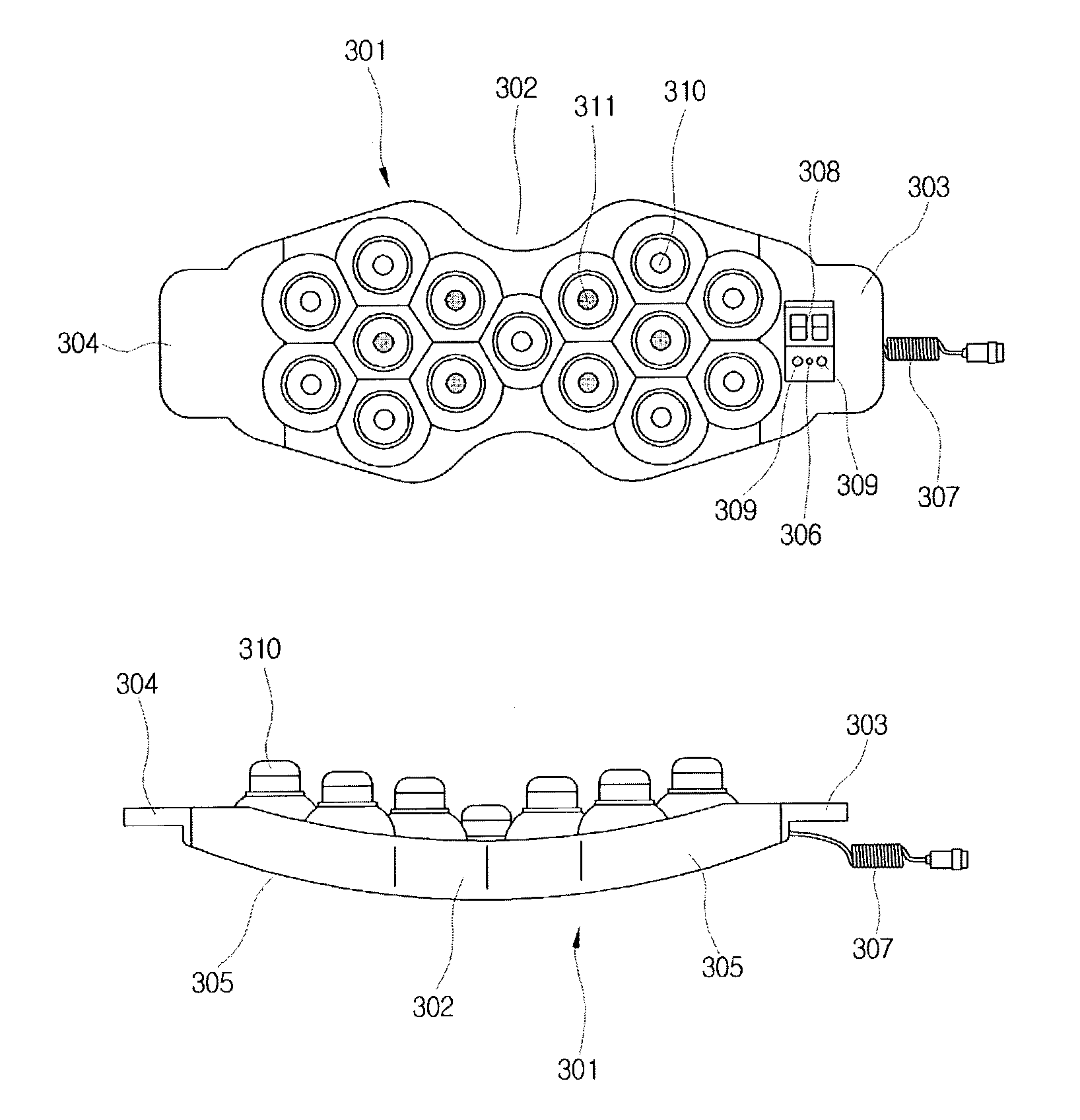
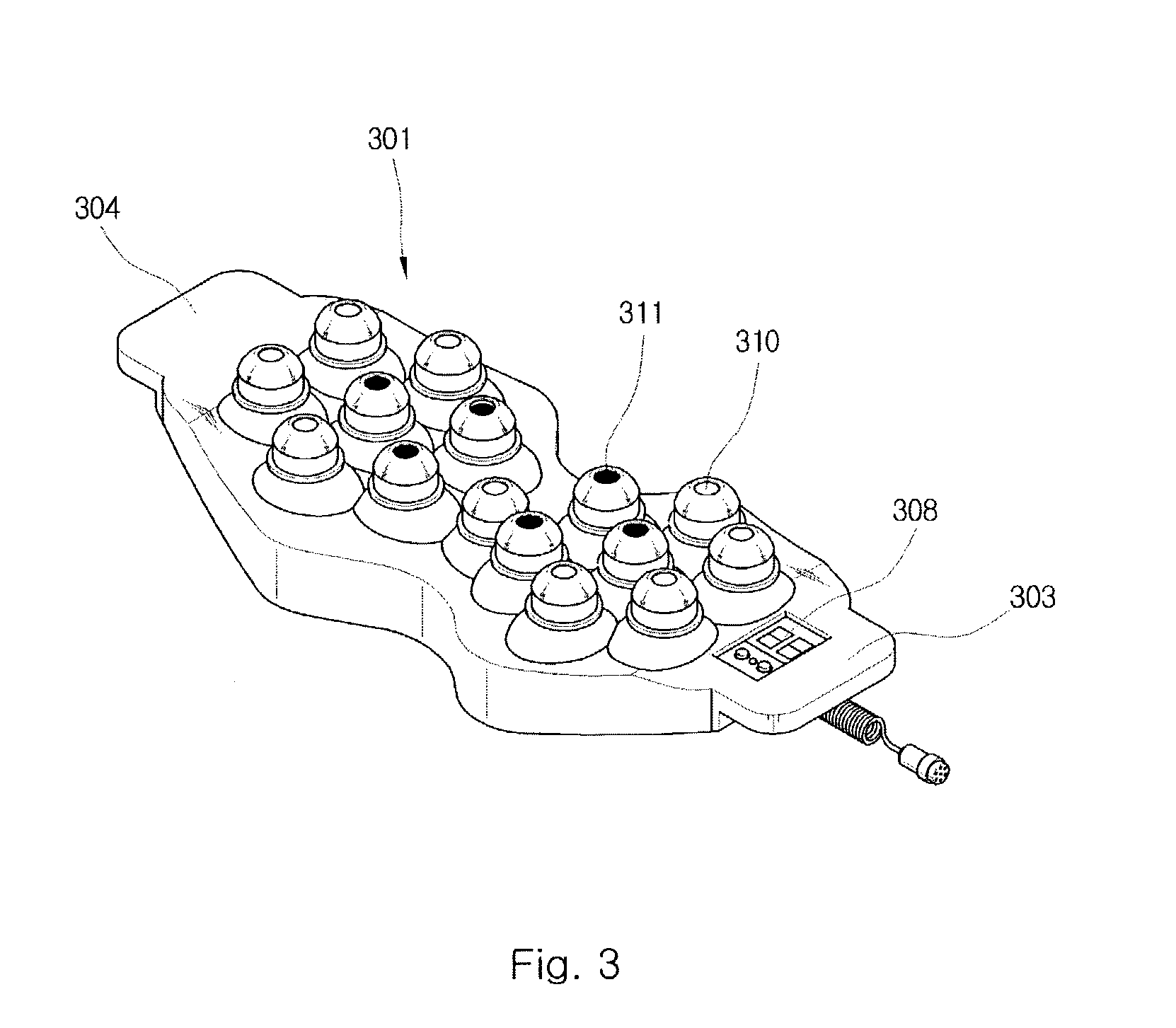
[0037]FIG. 3 is a perspective view illustrating a heat therapy device in accordance with the present invention. FIGS. 4a and 4b are a plan view and side view, respectively, illustrating the heat therapy device according to the present invention. As shown in FIGS. 3 to 4b, the heat therapy device, designated by reference numeral 301, comprises a middle portion 302, handles 303 and 304, both end portions 305, an ON / OFF button 306, an electric power line 307, a temperature display window 308, upper and lower temperature adjustment buttons 309 and 309′, acupressure knobs 310, and highly thermally conductive and far-infrared emitting material 311.

[0038]Considering the structure of the heat therapy device 301 according to the present invention in detail, it is provided at its upper surface with a plurality of upwardly protruding acupressure knobs 310, and each of the acupressure knobs 310 highly thermally conductive and far-infrared emitting material 311 attached to it. The middle portion...


PUM


Abstract

A heat therapy device and therapy system is provided comprising a plurality of acupressure knobs having superconductive and far-infrared emitting material attached to it. This therapy device is slightly bent up at both ends for comforting the patients. The therapy system is configured more than one therapy device comprising: upper and lower bodies, control boxes, upper control panels connected to the upper control boxes, motors installed under the upper and lower bodies, pulleys installed at the opposite the motors, upper and lower rails installed between the motors and pulleys, timing belts positioned between the upper rails and the lower rails that directly connected to the motors and pulleys; upper and lower mobile units coupled with the timing belts and seated on the upper and lower rails, each mobile unit installed with the multiple heat therapy devices, and other heat therapy devices formed the left and right sides of upper rails.

Description

BACKGROUND OF THE INVENTION[0001]1. Field of the Invention[0002]The present invention relates to a heat therapy device and a heat therapy system for applying acupressure and thermal treatment to aching parts of a patient's body using high-temperature heat and far-infrared rays emitted from the heat therapy device, thereby preventing and healing various diseases. More specifically, the present heat therapy device is provided on the upper surface thereof with a plurality of upwardly protruding acupressure knobs, to which highly thermally conductive and far-infrared emitting material is attached, and both side portions of the device are curved upward and are provided with handles.[0003]2. Description of the Related Art[0004]Generally, the human body has a plurality of vital acupuncture points. These acupuncture points have been widely utilized and developed in folk remedies. Namely, where acupressure and massage treatments are applied on the acupuncture points, cells of that compressed...

Claims


Application Information

Patent Timeline
Patent Type & Authority Patents(United States)
IPC IPC(8): A61F7/12A61H7/00A61H39/04A61H39/06A61N5/01A61N5/06
CPCA61H7/001A61H39/04A61H39/06A61N5/06A61N2005/066A61N5/01A61N5/0619A61H2201/10
Inventor PARK, MI-JA
Owner MIGUN MEDICAL INSTR
Why Eureka
Try Eureka