
Methods for reducing the viscous drag on a surface and drag reducing device

a technology of viscous drag and reducing device, which is applied in the direction of special-purpose vessels, vessel construction, transportation and packaging, etc., can solve the problems of incontestable mechanism for such reduction, inability to carry and replenish, and inability to detect the toxicity of additives, etc., to achieve large drag reduction, reduce drag, and reduce power input

Inactive Publication Date: 2006-05-16
BOARD OF RGT THE UNIV OF TEXAS SYST
View PDF10 Cites 18 Cited by
  • Summary
  • Abstract
  • Description
  • Claims
  • Application Information

AI Technical Summary

Benefits of technology

[0011]The invention has the potential to provide large drag reductions, comparable to those obtained with bubble cloud or polymer / surfactant injection, but without the large power input required for bubble cloud injection or the need to carry or generate chemical injectants.

Problems solved by technology

The major problems with such additives are that they must be carried and replenished and there remain concerns about toxicity of additives.
Similarly, the process of micro-bubble cloud injection has been found to dramatically reduce drag but an incontestable mechanism for such reduction has not been discerned.
Moreover, the energy cost of generating or injecting the bubbles may not be recovered from the drag benefits.
However, riblets as well as other very small scale surface textures (e.g., LEBUs) suffer from the problem of biofouling in practice and, anyway, appear limited to only a few percent improvement benefit at best.

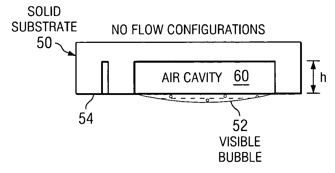
Method used


Image

  • Methods for reducing the viscous drag on a surface and drag reducing device
  • Methods for reducing the viscous drag on a surface and drag reducing device
  • Methods for reducing the viscous drag on a surface and drag reducing device

Examples


Embodiment Construction

A Trapped Bubble Array

[0017]Described in this section is the Trapped Bubble Array (TBA) concept with numerical and experimental results to date. It should be understood, however, that the principals of the TBA concept may be extended to other applications.

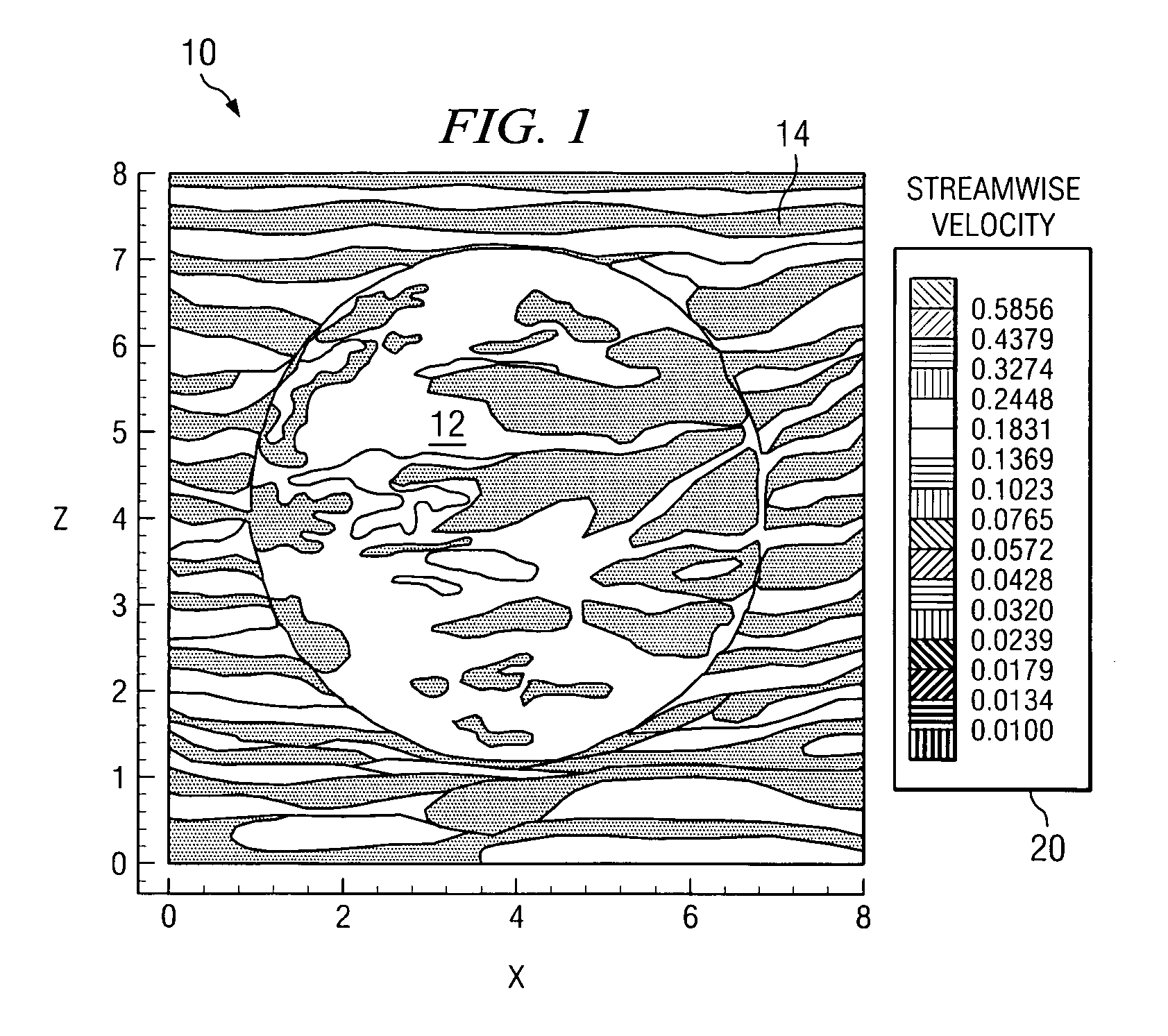
[0018]Consider the following gedanken experiment. We submerge a horizontal flat plate in a water channel and measure the drag on it. We may use a mechanical force balance or measure the velocity profile and perform a momentum balance computation. The flow develops a simple growing boundary layer from the leading edge.

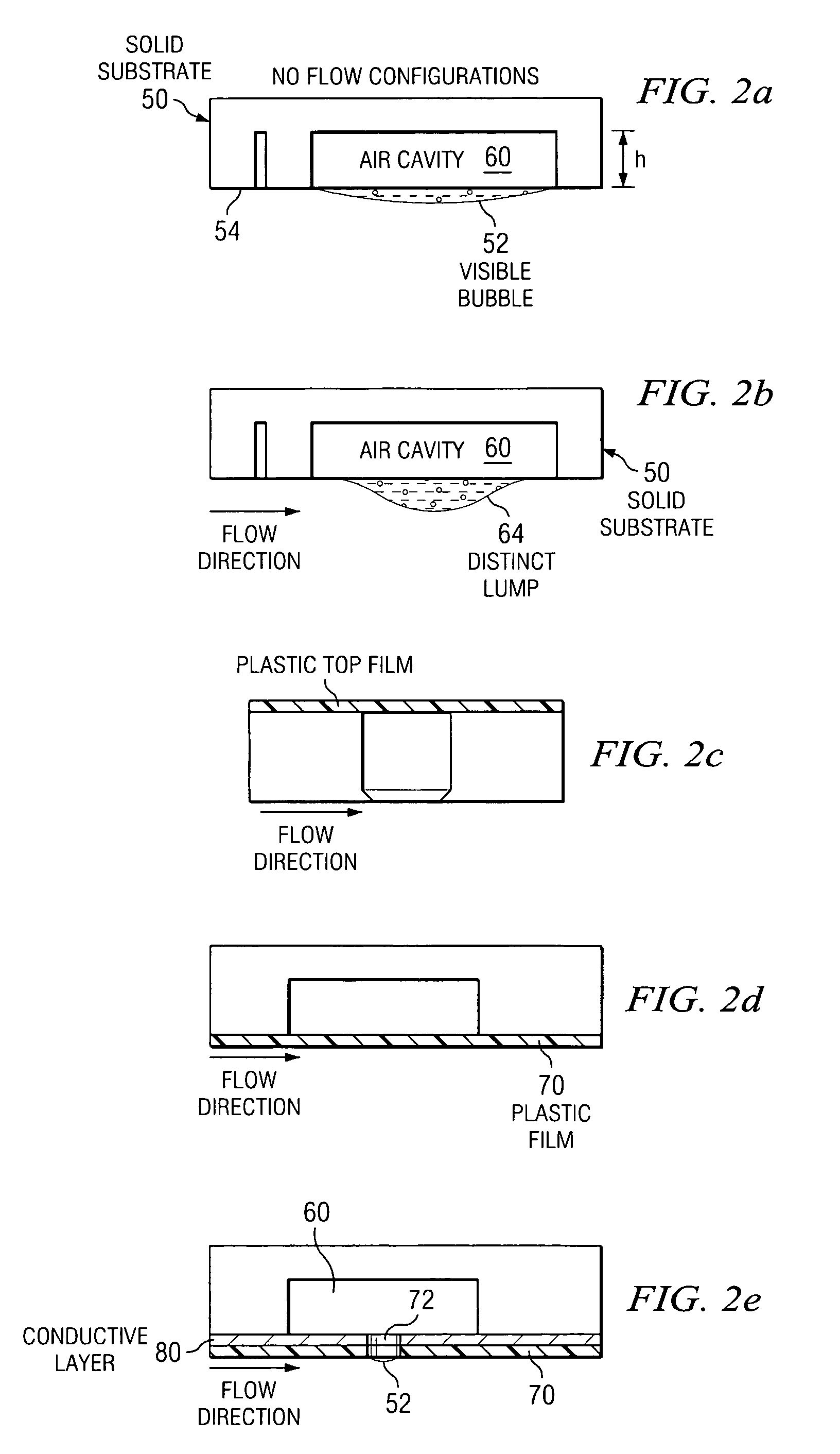
[0019]Now suppose we drill a hole up into the bottom of the plate (but not all the way through) and, using a syringe, inject enough air into the hole so that the bubble capping the hole is virtually flush with the flat plate surface. Will the drag on the plate with the hole be larger or smaller or the same as the drag on the smooth plate? It is suggested here that since the air / water interface is nearly free of shear s...


PUM


Abstract

A submerged surface is created, either as an add-on application or as an integral part of the submerged structure, having an array of closely spaced small bubble-filled holes which cover a large fraction of the wetted surface area. The viscous drag on the bubbles is much smaller than that on the surrounding solid surface and the net drag on the entire submerged surface is less than that on an equivalent solid surface.

Description

CROSS-REFERENCE TO RELATED APPLICATION[0001]This application is related to Provisional Application Ser. No. 60 / 375,878 entitled “A METHOD FOR REDUCING THE VISCOUS DRAG ON A SUBMERGED SURFACE,” by David B. Goldstein, filed Apr. 26, 2002, the entirety of which is incorporated herein by reference. This application claims priority of the aforementioned related provisional application.TECHNICAL FIELD[0002]The present invention relates generally to the reduction of viscous drag on solid surfaces and, particularly, to applications which may involve reducing the drag on submerged or semi-submerged fresh water or ocean-going vessels.BACKGROUND OF THE INVENTION[0003]Development of different means of boundary layer control, particularly as applied to viscous drag reduction, are essential to future development in the fields of ship design, aerodynamics, heat transfer, flow / structure interactions, and acoustics. For most engineering applications, a turbulent boundary layer in the fluid adjacent ...

Claims


Application Information

Patent Timeline
Patent Type & Authority Patents(United States)
IPC IPC(8): B63B1/34B63B1/36B63B1/38
CPCB63B1/34B63B1/38B63B1/36Y02T70/122Y02T70/121Y02T70/10
Inventor GOLDSTEIN, DAVID B.
Owner BOARD OF RGT THE UNIV OF TEXAS SYST
Learn More