Reciprocating system with buoyant aircraft, spinnaker sail, and heavy cars for generating electric power

a technology of electric power generation and reciprocating system, which is applied in the direction of electric generator control, machine/engine, greenhouse gas reduction, etc., can solve the problems of inability to sell or use such units, the vulnerability of polymers in the envelope to damage and degradation by ultraviolet radiation, and the failure of the company to achieve the effect of reducing the efficiency of wind turbines, increasing the power input, and increasing the force, power and work

Inactive Publication Date: 2011-09-13
TETRAHEED
View PDF4 Cites 49 Cited by
  • Summary
  • Abstract
  • Description
  • Claims
  • Application Information

AI Technical Summary

Benefits of technology

[0063]The zeppelin will be inflated and deflated in a repeating cycle, using efficient equipment to recapture as much energy as possible during each expansion stage of the gas-handling cycle. Reaching the first peak of “stored energy”, by pumping hydrogen or helium into high-pressure tanks, will require a large power input; however, when the gas is later allowed to leave the tanks and enter an unpressurized balloon, much of that energy can be recovered, in a manner comparable to cyclic compression and decompression of a spring. Accordingly, it is believed that this type of closed gas-handling cycle, if designed and run properly, can run for numerous cycles without requiring large amounts of additional energy input.
[0064]In addition to using gas-filled buoyant aircraft, this system also uses spinnaker-type sails to generate large wind-driven forces that can help lift a heavy car to the top of its rail track, during the ascent stage of each cycle. Such sails can generate substantially greater force, power, and work than wind turbines, because of two major factors. First, the blades of a wind turbine occupy only a small fraction (roughly 5% or less) of the “swept area” that is traversed by the rotor blades, while “unused” wind simply blows through the huge majority of the swept area, without transferring any power to a mechanical system. Second, the sloping surfaces of wind turbine blades must convert wind power that is moving in one direction, into mechanical power that is moving perpendicular to the direction of the wind. That required “direction change” further reduces the efficiency of wind turbines. Accordingly, both of those factors greatly reduce the amount of actual power generation by wind turbines, and both of those factors can be avoided and eliminated, if a spinnaker sail is coupled to a cable and pulley system, and used to repeatedly pull a massive and heavy car to the highest point on a sloping or vertical track.

Problems solved by technology

However, since “dirigible” is a dissonant word that does not sound appealing or translate well, and since the aircraft herein are designed to be blown by the wind while tethered to the ground, rather than flown and steered under their own power, it also is not preferred for use herein.
That company did not succeed.
Illustrations, press releases, and more information can be found by searching the Internet for “skyhook”; however, it is not clear whether any such units have been actually sold, or whether they are in actual use.
It does not appear to be in commercial use, and questions arise about whether it is practical, in view of the high winds in the upper atmosphere (which presumably would keep such a system constantly moving), and the vulnerability of polymers in an envelope to damage and degradation by ultraviolet radiation, which is much stronger at such heights than at ground level.
None of those systems are designed or intended for a repeated and frequent cycling operation, in which helium or hydrogen gas is cycled back and forth between high-pressure tanks, and a low-pressure zeppelin envelope.
It also states that the pumps / compressors and high-pressure tanks can be carried directly by the zeppelin, if desired, in a way that can eliminate one of the four layers of the complete lift-and-launch system; however, that design would not be optimal, and it would eliminate and lose a set of useful components that can help the system make a high-altitude transition from slow ascent, to high-speed flight.
The extent of the increased improved lifting efficiency that can be gained, by incorporating a buoyant craft such as a zeppelin in a lifting ferry, cannot be reliably estimated or predicted by the Applicant, who does not have the computer-modeling resources that are available to aircraft companies and engineering colleges.
In a typical non-hybrid car, the brakes do nothing to harvest any useful work or power.
Instead, brakes stop a car by using friction, which heats up the brake pads and wheel rotors; those brake pads and rotors then dissipate that useless heat, to the atmosphere.
Accordingly, if those two different types of reciprocating cycles are coupled together, a potential paradox would appear to arise.
However, on a practical and reasonable level, there is no good reason not to regard “all of planet earth” as a reasonably complete and self-contained system, and there is no compelling reason to not regard the entire future of this planet as a relevant, practical, and appropriate operating “lifetime” for a machine.
However, after those steps are complete, wind turbines can extract energy from an essentially free and unlimited resource, over an operating life that will last for decades.
They will always and inevitably consume more electric power, at night, than they generate during the day.
These “losses” mainly involve friction-type heating of the water, when it is pumped up a hill, and when it runs down through a pipe and turbine.
Water is very efficient in soaking up and absorbing heat energy, thereby creating useless energy “sinks” that reduce the efficiency of any power-handling system that involves water.

Method used


Image

  • Reciprocating system with buoyant aircraft, spinnaker sail, and heavy cars for generating electric power
  • Reciprocating system with buoyant aircraft, spinnaker sail, and heavy cars for generating electric power
  • Reciprocating system with buoyant aircraft, spinnaker sail, and heavy cars for generating electric power

Examples


Embodiment Construction

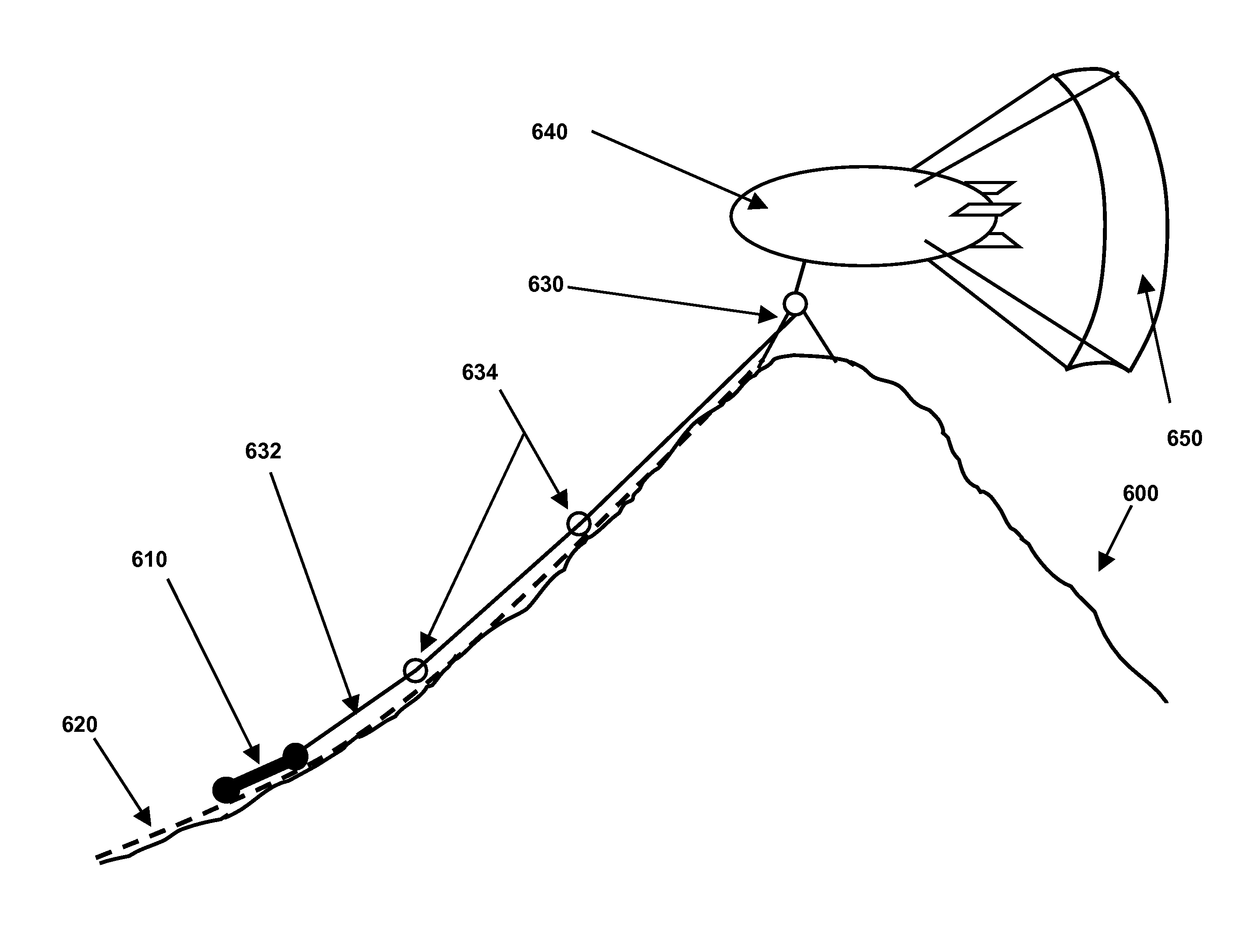
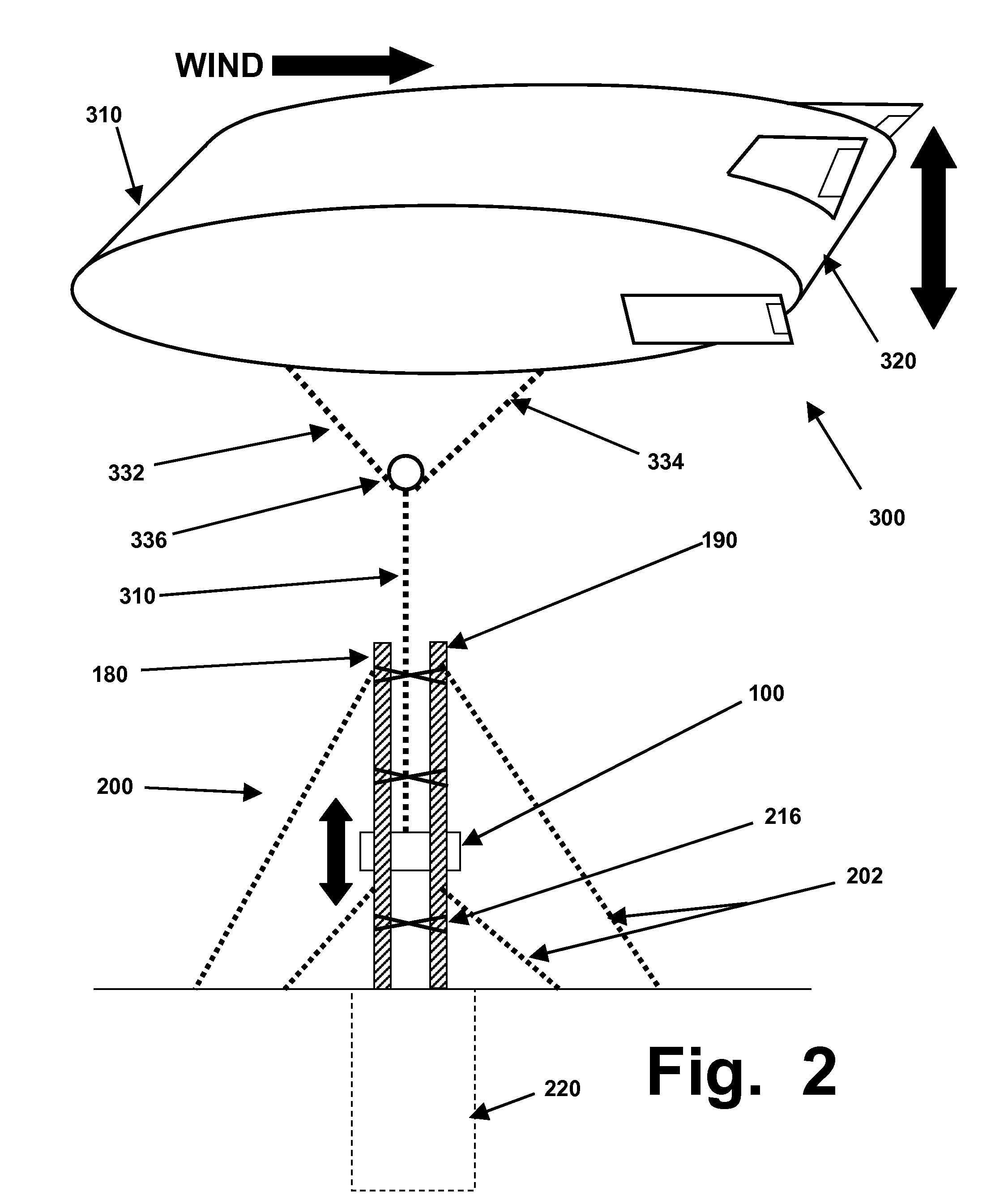
[0072]As briefly summarized above, either and preferably both of two types of lifting and pulling devices (a helium- or hydrogen-filled zeppelin, and a spinnaker-type sail) are used to lift a heavy traveling unit (which can also be called a reciprocating or cycling weight, car, unit, or similar terms) to an elevated height, such as on a vertical or sloping track installed in a tower assembly, in or alongside a tall building, or on a slope of a large hill or mountain. After the heavy car reaches its highest point of ascent, it is released from the pulling and lifting device(s), and it descends down the track, using its weight and motion to generate electric power as it descends.

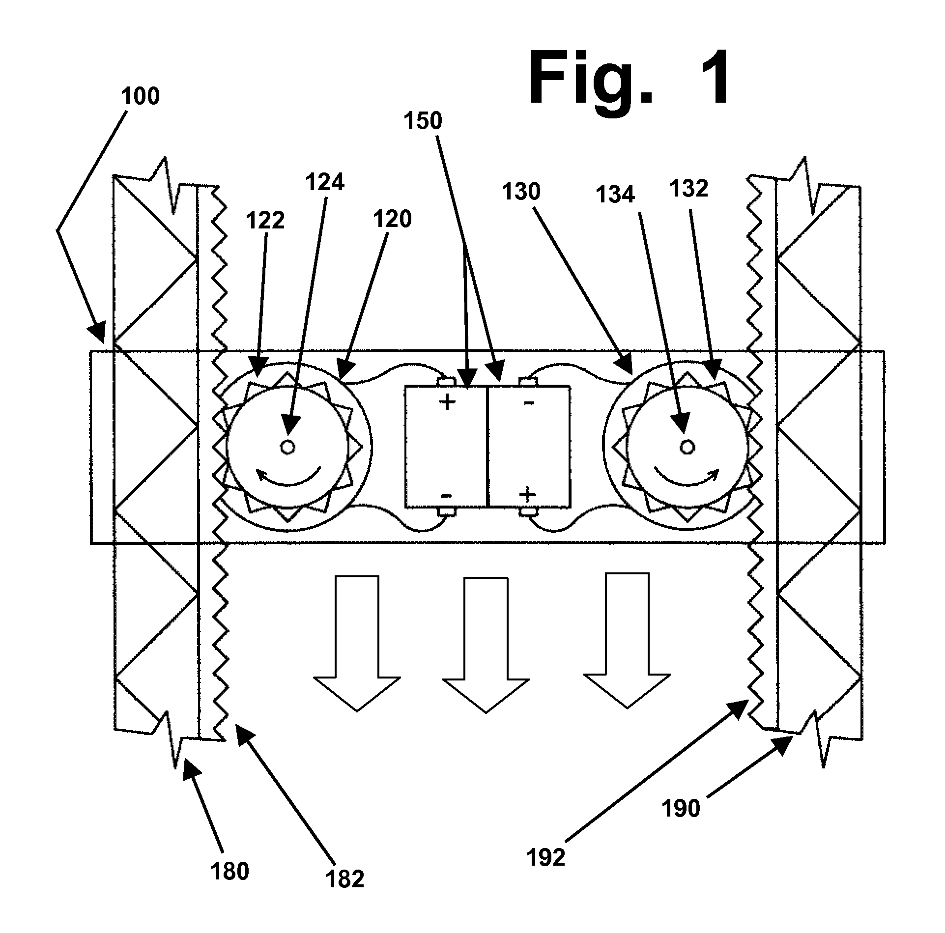
[0073]In one preferred embodiment, the heavy car can contain one or more large generators, and will use metallic wheels, or other brushes or contacts, to continuously transfer electric current from the generator(s) into the rail system, as the heavy car descends. In a second preferred embodiment, the heavy car...


PUM


Abstract

An electric generating system uses a zeppelin filled with helium or hydrogen, and a spinnaker sail, to provide pulling power that will lift a heavy railcar to an elevated height on a track, such as on a hill or mountainside, or in an elevator-type shaft in a tall building. When the heavy car reaches the top of the track, it is released, and its descent drives an electric generator. The generator can be carried by the car, and can send the power to batteries on the car, or to conductive rails. Alternately, if the car is inert weight, cables can drive stationary generators. The zeppelin will be inflated and deflated repeatedly, using equipment to recapture energy during each gas expansion, to help drive subsequent recompression into high-pressure tanks. The spinnaker sail will use a cable-handling device and spreader bars to deploy the sail and keep it at an elevated height. Various advantages are provided compared to wind turbines and pumped-storage hydroelectric facilities.

Description

BACKGROUND[0001]This invention is in the field of electromechanical systems, and relates to the use of buoyant aircraft (such as zeppelins filled with hydrogen or helium) with spinnaker-type sails to generate electric power.[0002]Several terms that apply to buoyant aircraft should be briefly addressed. These terms overlap heavily, and any of them can be applied to the types of buoyant aircraft of interest herein. However, several of these terms have potentially misleading connotations, and therefore should be avoided.[0003]Technically, the buoyant aircraft of interest herein can be called “balloons”, since they will have flexible enclosures (which also can be called envelopes, bags, skins, bladders, or similar terms) that can be reversibly inflated and deflated. However, in the context of buoyant aircraft, “balloons” tends to imply hot air balloons with spherical rather than elongated shapes, so “balloon” is not preferred for use herein.[0004]These buoyant aircraft also can be calle...

Claims


Application Information

Patent Timeline
Patent Type & Authority Patents(United States)
IPC IPC(8): F02B63/04
CPCF03D5/04F03D9/021F05B2240/921F05B2240/922F05B2240/98Y02B10/30Y02E10/70Y02E10/72F03D9/11F03D9/25Y02E70/30
Inventor KELLY, PATRICK D.
Owner TETRAHEED
Why Eureka
Try Eureka