Bulk material pump feeder with reduced disk jamming

Inactive Publication Date: 2006-05-16
K TRON TECH INC
View PDF29 Cites 54 Cited by
  • Summary
  • Abstract
  • Description
  • Claims
  • Application Information

AI Technical Summary

Benefits of technology

[0009]Three structural embodiments or features of the bulk materials pump feeder reduce the tendency of material to jam between the drive rotor and the housing or other stationary parts mounted to the housing. First, the distance between the circumferential edges of the drive disks and the housing inner wall increases from the inlet to the outlet in the direction of rotation of the drive rotor. Second, a low-friction brush seal dispose

Problems solved by technology

Second, a low-friction brush seal disposed on the periphery of the drive disk

Method used


Image

  • Bulk material pump feeder with reduced disk jamming
  • Bulk material pump feeder with reduced disk jamming
  • Bulk material pump feeder with reduced disk jamming

Examples


first embodiment

[0025]A. First Embodiment

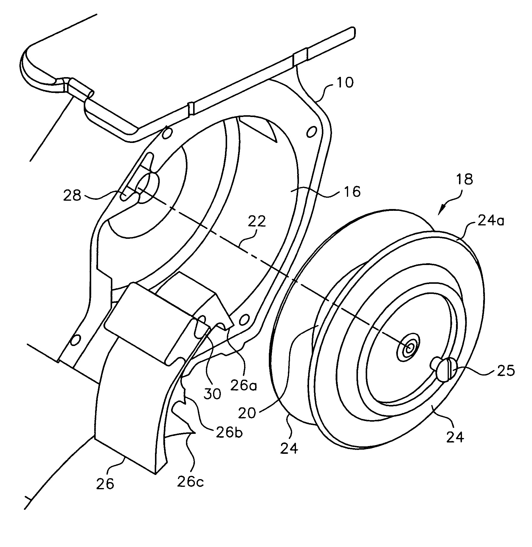
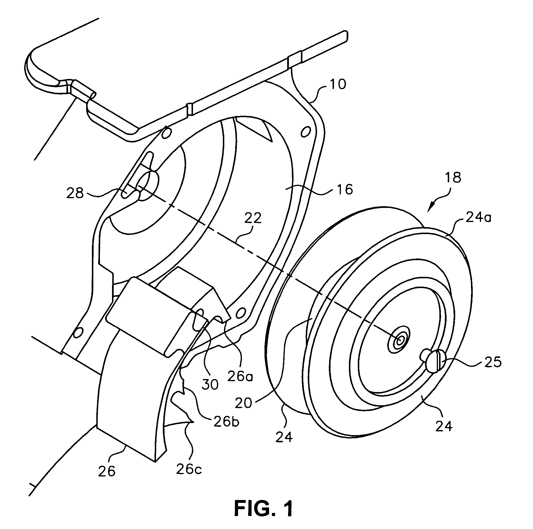
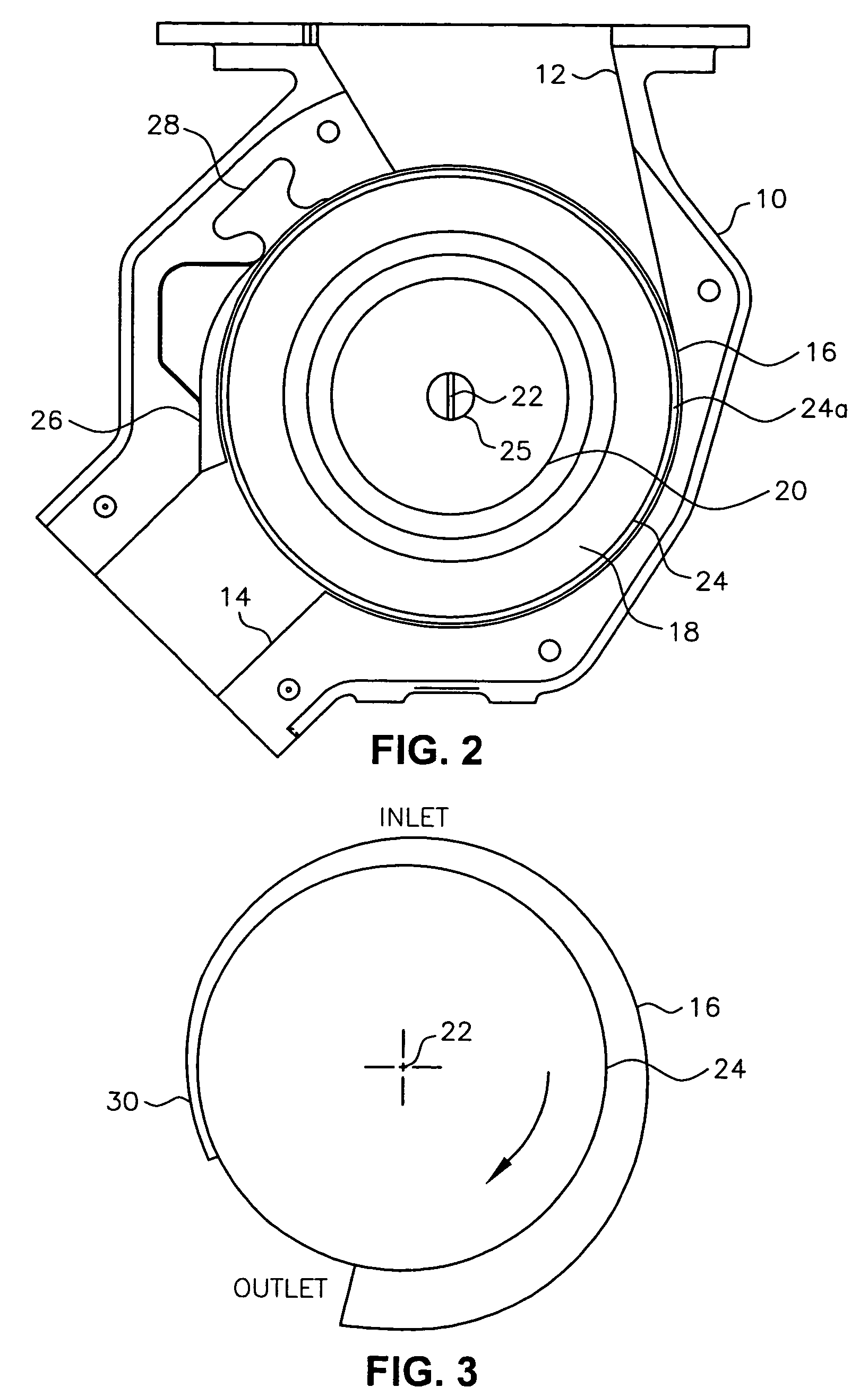
[0026]As shown most clearly in FIG. 3, which is a schematic drawing of the relationship between drive disks 24 and inner wall 16 of housing 10, the distance between the circumferential edges of drive disks 24 and inner wall 16 of housing 10 increases from INLET 12 of housing 10 to OUTLET 14 of housing 10 in the direction of rotation of drive rotor 18, which is clockwise as indicated by the arrow for the embodiment of the invention illustrated in the figures and being described. Drive disks 24 and inner wall 16 of housing 10 can be shaped in different ways to provide the desired spacing between the two components. For the embodiment of the invention illustrated in the figures and being described, drive disks 24 are circular and extend away from hub 20 perpendicular to rotation axis 22 of hub 20, and inner wall 16 of housing 10 is spiral shaped. The spiral-shaped inner wall 16 of housing 10 can be defined by the Archimedes spiral equation:

R=θ*a

where: “R” is th...

second embodiment

[0036]B. Second Embodiment

[0037]In the second embodiment of the present invention, as illustrated in FIGS. 6 and 7, a low-friction brush seal 50 is disposed on the periphery of drive disks 24. Brush seal 50 may be made of a number of different materials including, for example, pipe cleaner and rope. Brush seal 50 also may be constructed by combining a base made of metal, such as carbon steel, stainless steel, or aluminum, with a non-metallic brush made of a natural or synthetic fiber.

[0038]It is not necessary that brush seal 50 form a perfect seal between the periphery of drive disks 24 and inner wall 16 of housing 10. Although a small amount of contact occurs between brush seal 50 and inner wall 16 of housing 10, brush seal 50 induces little or no friction between drive disks 24 and inner wall 16 of housing 10 as drive disks 24 rotate. A low-friction seal is important to avoid an extra load on the drive motor. Moreover, the addition of brush seal 50 does not introduce tolerance iss...

third embodiment

[0045]C. Third Embodiment

[0046]In the third embodiment of the present invention, as illustrated in FIGS. 8 and 9, a third form of materials scraper 56 is provided. As illustrated in FIG. 8, materials scraper 56 may have a continuous scraping surface 40 like materials scraper 36 of FIG. 5. Alternatively, as illustrated in FIG. 9, materials scraper 56 may have a plurality of scraping tips 26a, 26b, and 26c as does materials scraper 26 shown in FIG. 4.

[0047]The function of materials scraper 56 is to scrape the materials handled by the bulk materials pump feeder from drive disks 24 and hub 20 as the materials exit the bulk materials pump feeder. For many materials, such scraping is unnecessary. Materials scraper 56 is especially adapted for those applications which require no or only a minimal amount of scraping. Specifically, relative to materials scraper 26 of FIG. 4 and materials scraper 36 of FIG. 5, a majority of the structure forming materials scraper 56 has been eliminated (shown...


PUM


Abstract

A bulk materials pump feeder having a housing and a rotating drive rotor for transferring material from an inlet to an outlet of the housing. The drive rotor has a hub. Drive disks extend away from the hub toward a housing inner wall. Three structural features of the feeder reduce the tendency of material to jam between the drive rotor and the housing or other stationary parts. First, the distance between the circumferential edges of the drive disks and the housing inner wall increases from the inlet to the outlet in the direction of rotation of the drive rotor. Second, a low-friction brush seal disposed on the periphery of the drive disks seals the area between the periphery of the drive disks and the inner wall. Finally, a materials scraper having a flexible tip is mounted in the housing and extends into the drive rotor between the drive disks.

Description

RELATED APPLICATION[0001]The present application is a continuation-in-part of pending U.S. patent application Ser. No. 10 / 119,359 filed on behalf of inventors Timothy R. Baer and James T. Foley on Apr. 9, 2002 now U.S. Pat. No. 6,832,887, titled “Bulk Material Pump Feeder,” assigned to the assignee of the present application, and incorporated in this application by reference.TECHNICAL FIELD[0002]The present invention relates, in general, to materials handling equipment and, in particular, to a pump feeder of materials handling equipment that feeds bulk materials.BACKGROUND OF THE INVENTION[0003]In certain bulk materials handling equipment, such as the equipment described and illustrated in U.S. Pat. No. 5,051,041 and U.S. Pat. No. 5,355,993, a pump feeder moves bulk material through a housing from an inlet to an outlet by a rotating drive rotor having two or more drive disks mounted to or integral with a rotating hub. In the past, this type of equipment has been used for feeding coa...

Claims


Application Information

Patent Timeline
IPC IPC(8): B65G31/04B65G53/42F04D7/04F04D29/22F04D29/42
CPCB65G31/04B65G53/46F04D7/045F04D15/0077F04D23/003F04D29/445F04D29/2266F04D29/2288F04D29/4206F04D29/426F04D29/167F04D5/00F04D7/04F04D29/18
Inventor BAER, TIMOTHY R.FOLEY, JAMES T.
Owner K TRON TECH INC
Why Eureka
Try Eureka