Membrane diffuser with uniform gas distribution

a membrane diffuser and gas distribution technology, applied in the direction of fuel gas production, transportation and packaging, carburetting air, etc., can solve the problems of uneven deflection of membranes, unfavorable uniform air distribution, etc., to increase gas transfer efficiency and enhance the uniformity of distribution

Inactive Publication Date: 2006-05-16
ENVIRONMENTAL DYNAMICS INC
View PDF17 Cites 40 Cited by
  • Summary
  • Abstract
  • Description
  • Claims
  • Application Information

AI Technical Summary

Benefits of technology

[0011]It is the principal goal of the present invention to provide a flexible membrane that is constructed to enhance the uniformity of distribution of gas to a liquid in a diffusion process in order to increase the gas transfer efficiency.
[0014]A further object of the invention is to provide a diffuser membrane of the character described in which the perforation area per unit of surface area on the membrane can be controlled in a variety of ways, including controlling the length of the membrane slits in different zones on the membrane, controlling the separation between adjacent slits, and controlling the spacing between adjacent rows of slits, circles of slits or other slit patterns, as well as other ways of achieving the desired result.
[0015]Yet another object of the invention is to provide a diffuser membrane of the character described which can be constructed in a simple and economical manner, which functions reliably over an extended operating life, and which can be used in various types, sizes and shapes of gas diffusers.
[0016]In accordance with the invention, an improved membrane is constructed in a manner to enhance the uniformity of gas distribution provided by a tubular disk or panel membrane. In a preferred embodiment of the invention, the areas of the membrane that are at the highest elevation are provided with the least total perforation area per unit area of the membrane. As a consequence, the gas discharge in these areas is more closely balanced with the gas discharge in the areas of the membrane that are subjected to a larger hydraulic head. The result is that the gas is distributed more uniformly throughout the entire area of the membrane, and the efficiency of the gas transfer is increased accordingly.
[0017]In the case of the tubular membrane, the circular cross-section of the membrane may be zoned into a first zone that occupies an arc centered at a north pole location on the membrane and at least two other zones occupying arcs located adjacent to the ends of the first zone. The perforations may be formed in spaced apart rows of slits, with the slits in each row spaced apart end to end and the rows spaced apart from one another (or another slit arrangement can be used). In the first zone which is deflected the most, the slits collectively occupy an area that is less per unit area on the membrane than is occupied by the slits in the other zones. This makes the gas discharge more uniform throughout the surface area of the membrane. The slits in the first zone can be made shorter or spaced further from adjacent slits, or the rows can be spaced further apart, or any combination of these techniques can be used to create a lesser overall percentage of the first zone that is occupied by the slits there. In the case of other perforation patterns, the perforations can be arranged to provide a greater collective area per unit membrane area in the lower parts of the membrane, thus enhancing the uniformity of the air discharge.
[0021]The membrane construction of this invention results in optimum distribution of gas, uniformity of gas discharge across the membrane surface, optimum pressure drop across the membrane thickness, and maximum efficiency in the transfer of gas to a liquid.

Problems solved by technology

Although these membrane diffusers function well for the most part, they are not wholly free of problems.
When gas pressure is applied, the membranes deflect unevenly.
The uniformity of the air distribution thus suffers, and the gas transfer efficiency decreases with the decrease in the uniformity of the gas distribution over the surface of the membrane.
The greater deflection of the center area of the membrane may also result in the perforations there opening to a greater extent, and this may aggravate the lack of uniform gas release.
Panel diffusers are subject to the same problems as disk diffusers as to the non-uniformity of the gas distribution caused primarily by the differential in elevation between the center area and the edge areas when the membrane is deflected less than the center area.
Again, this detracts from the uniformity of the distribution over the membrane surface and results in a lower gas transfer efficiency than in the case of more uniform distribution.
However, non-uniformities are still present and this technique has not completely solved the problem.
Tubular membranes are most efficiently manufactured using an extrusion process, so the tubular membrane cannot be tapered as readily as a disk membrane which is normally molded.
However, this results in significant added energy consumption which can increase the operating costs to unacceptable levels.
Therefore, the choices have been either to operate the diffuser with poor distribution or create a large head loss, neither of which is desirable from a performance or energy efficiency standpoint.

Method used


Image

  • Membrane diffuser with uniform gas distribution
  • Membrane diffuser with uniform gas distribution
  • Membrane diffuser with uniform gas distribution

Examples


Embodiment Construction

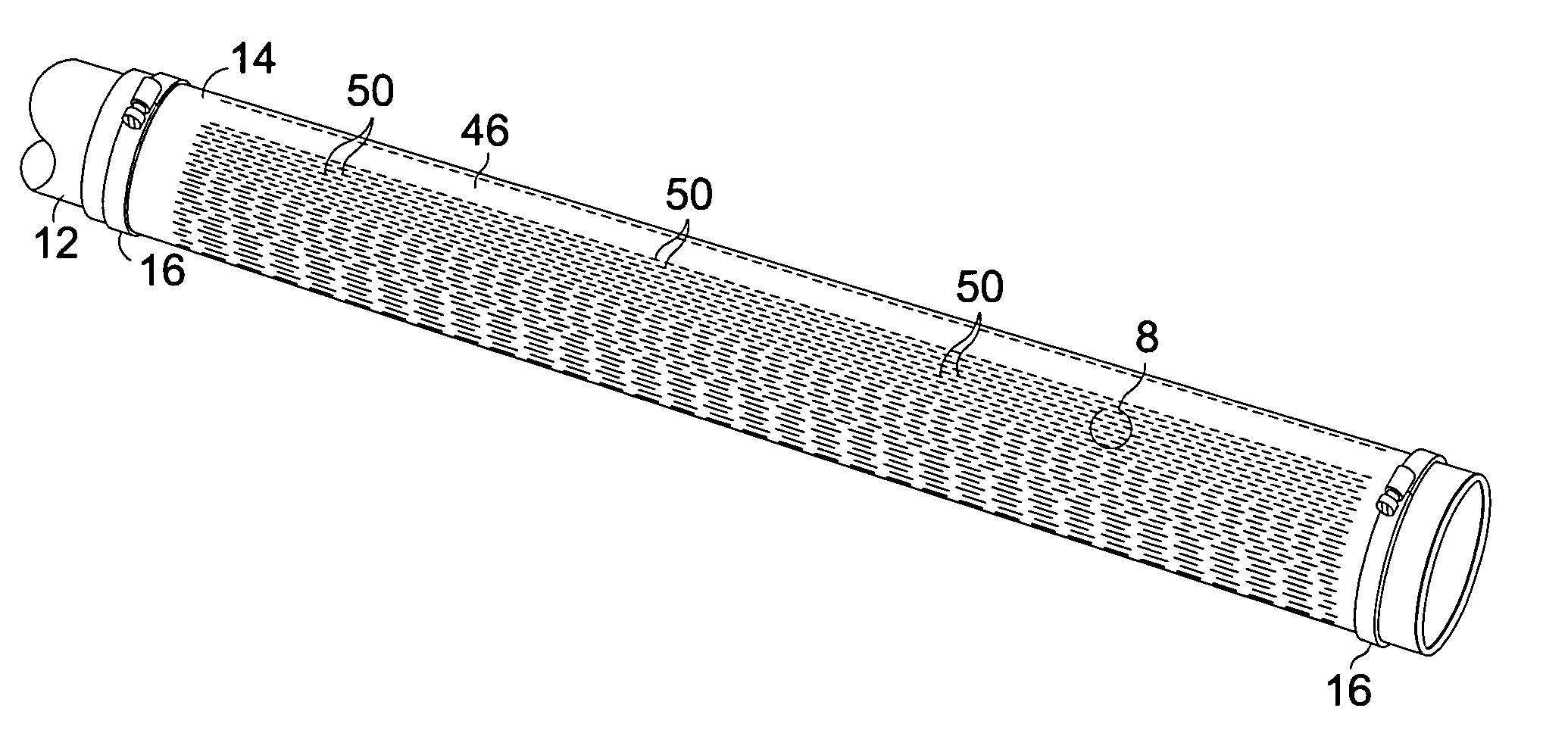
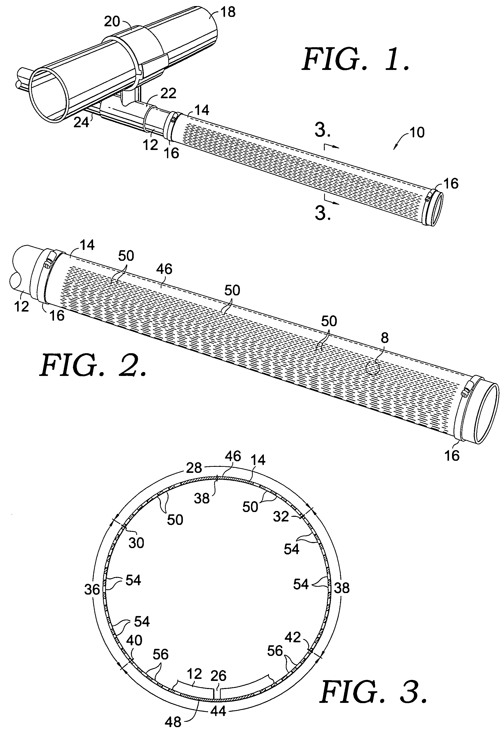
[0034]Referring now to the drawings in more detail and initially to FIG. 1, numeral 10 generally designates a tubular membrane diffuser constructed according to one embodiment of the present invention. The diffuser 10 includes a rigid cylindrical pipe 12 and a cylindrical membrane 14 which is sleeved closely around the pipe 12 and secured in place to the pipe by hose clamps 16 applied to the opposite end portions of the membrane 14, or by some other suitable means. The diffuser body or pipe 12 may be constructed of PVC or another suitable material.

[0035]In a typical application, the diffuser 10 is supplied with air or another gas from a submerged supply pipe 18 to which the gas is supplied by a fan or blower (not shown). A saddle structure 20 may be clamped onto the supply pipe 18 and provided with an outlet that applies the gas to the inlet of a tee fitting 22 suitably secured to the saddle 20. The diffuser pipe 12 is secured in one outlet of the tee fitting, and a similar diffuser...


PUM

PropertyMeasurementUnit
lengthaaaaaaaaaa
lengthaaaaaaaaaa
lengthaaaaaaaaaa

Abstract

A flexible diffuser membrane is provided with a unique system of perforations arranged to result in uniform distribution of gas even though the membrane deflects to different extents or the submergence varies in different parts of the membrane. The perforations are arranged to provide less perforation area per unit of perforated membrane surface area in the membrane parts that deflect the most or are submerged least and greater perforation area in membrane parts that deflect the least or are submerged most. The perforations can be slits arranged in parallel rows on a tubular membrane, in concentric circles or another pattern on a disk membrane, or in still a different pattern on a flat panel diffuser membrane. The slit length or separation can be varied between different zones on the membrane surface or the spacing between rows or circles can be varied.

Description

FIELD OF THE INVENTION[0001]This invention relates generally to the diffusion of gases into liquids and deals more particularly with membrane diffusers which discharge gas into a liquid in the form of fine bubbles.BACKGROUND OF THE INVENTION[0002]In the various applications for diffusing gas into liquids, such as in the aeration of wastewater, it is known that the highest efficiency is achieved when the gas is released as fine bubbles. The efficiency in transferring oxygen or another gas to the liquid is enhanced by maximizing the bubble surface area compared to the volume. Consequently, the gas transfer efficiency increases directly with decreasing bubble diameter, so fine bubbles result in a more efficient process.[0003]Fine bubble technology has made use of tube diffusers that include a flexible membrane sleeved onto a tube diffuser body and provided with small perforations for discharging the gas into the liquid. When gas pressure is applied inside of the membrane, the membrane ...

Claims


Application Information

Patent Timeline
Patent Type & Authority Patents(United States)
IPC IPC(8): B01F3/04
CPCB01F3/04269B01F2003/04319B01F2003/04326Y10S261/70B01F2003/04404B01F2215/0052B01F2003/04368B01F23/23124B01F23/231266B01F23/231232B01F23/231265B01F23/231244B01F2101/305B01F23/231242
Inventor THARP, CHARLES E.
Owner ENVIRONMENTAL DYNAMICS INC
Why Eureka
Try Eureka