

Wheel supporting roller bearing unit and manufacturing method of the same
a technology of supporting roller bearings and manufacturing methods, which is applied in the direction of bearing unit rigid support, braking discs, braking systems, etc., can solve the problems of rotor deflection, difficult to achieve complete squareness, vibrations accompanied by uncomfortable noises
- Summary
- Abstract
- Description
- Claims
- Application Information
AI Technical Summary
Benefits of technology
Problems solved by technology
Method used
Image

Examples
embodiment 1
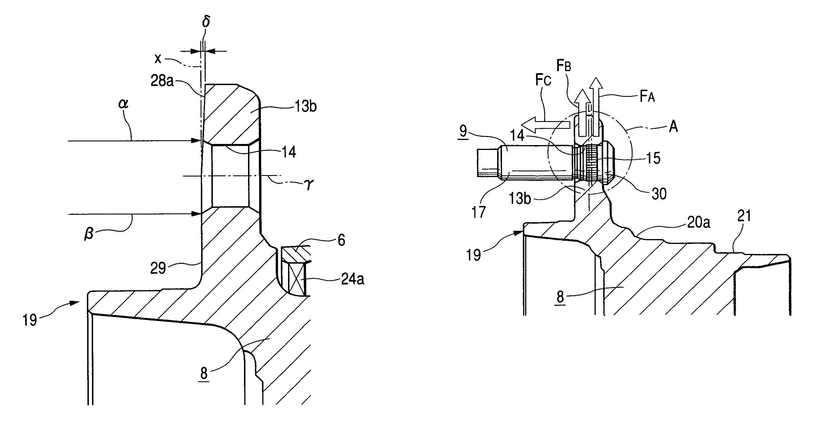
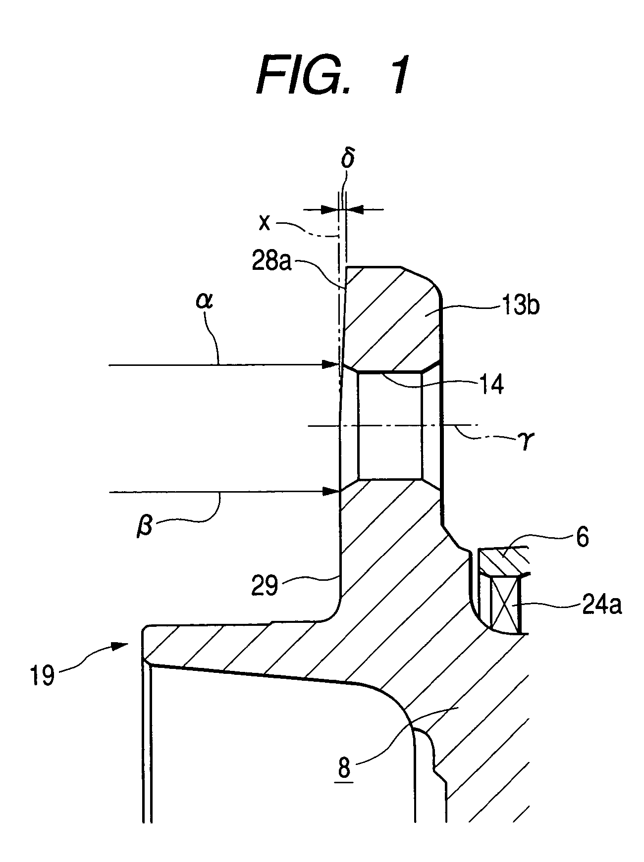
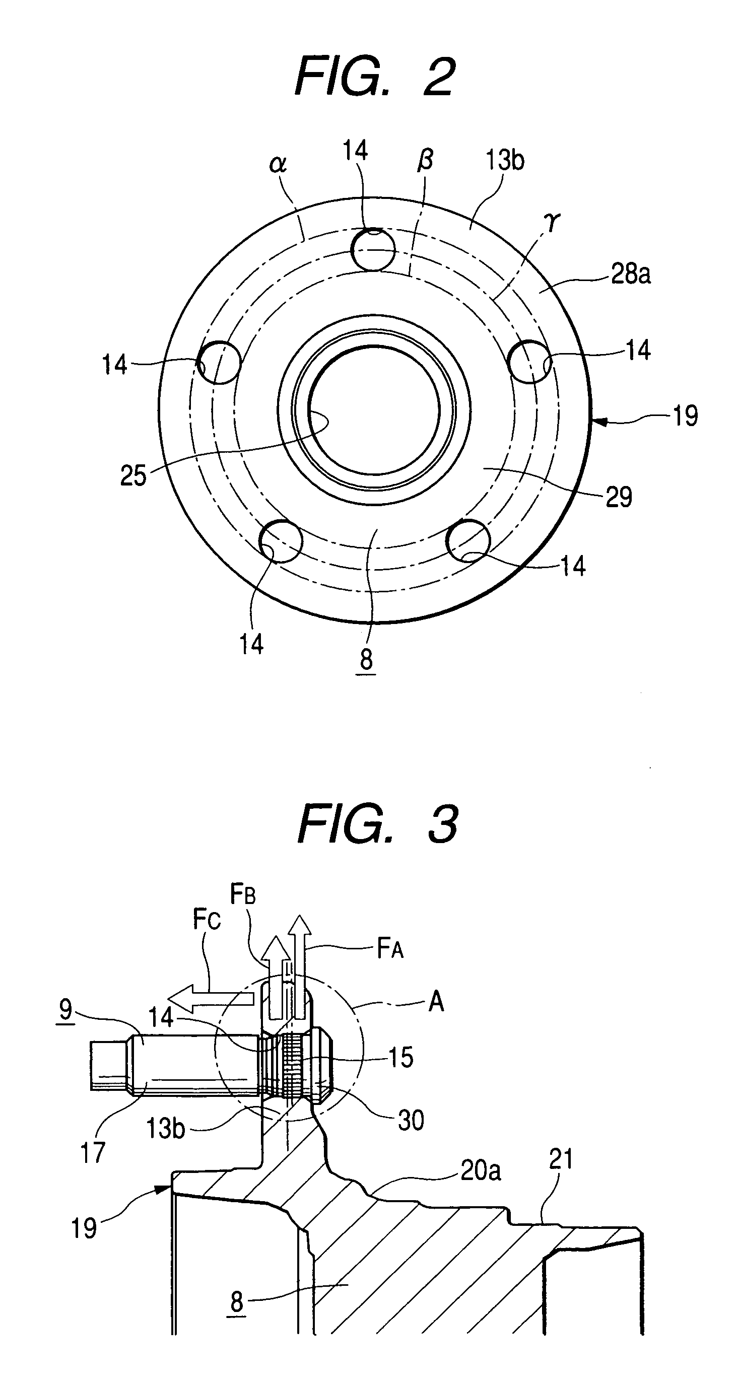
[0052]FIGS. 1 to 4 show Embodiments 1 to 4 of the invention. Here, the invention is characterized in the following point. Even in case a mounting flange 13b of a hub body 8 constructing a hub 19 is deformed as the serrated portions 15 of studs 9 are individually press-fitted into a plurality of mounting holes 14 and 14 formed in the mounting flange 13b, a rotor 10 (FIG. 10) jointed and fixed to the mounting flange 13b is prevented from having its side face deflected in the axial direction. The constructions and actions of the remaining portions are similar to those of the aforementioned structure shown in FIG. 10. Therefore, the illustrations and descriptions of the similar portions will be omitted or simplified, and the following description will be centralized in the characterizing portions of the invention.
[0053]Before the serrated portions 15 of the studs 9 are press-fitted into the individual mounting holes 14 and 14, a taper face 28a is formed at such a portion of the mounting...
embodiment 2
[0063]FIG. 5 shows Embodiment 2 of the invention. In the case of this embodiment, too, at the radially outer portion of one side face (or the outer side face) of a mounting flange 13c, there is formed a taper face 28b, which is inclined to come the closer to the other side face of the mounting flange 13c as it goes the farther to the radially outer side. Especially in the case of this embodiment, this taper face 28b has its inner circumference edge located at the portion of the inscribed circle β of the individual mounting holes 14. Even if the radially inner portion of the one side face of the mounting flange 13c than the pitch circle γ of the individual mounting holes 14 is deformed as the serrated portions of the studs 9 are press-fitted into the individual mounting holes 14, therefore, that radially inner portion hardly causes the deflection of the rotor 2 (as referred to FIG. 10). The remaining constructions and actions are similar to those of the aforementioned Embodiment 1.
embodiment 3
[0064]FIGS. 6 to 8 show Embodiment 3 of the invention. In the case of this embodiment, with the flanged portions 30 formed at the root end portions of the individual studs 9 being in abutment against a mounting flange 13d, the serrated portions 15 of the individual studs 9 are located at positions offset from the center to the one side face of the mounting flange 13d with respect to the thickness direction of the mounting flange 13d. For this offset location, the serrated portions 15 are formed closer to the centers of the studs 9, as shown in FIG. 7, or counter-sunk portions 31 are formed around the other side openings of the mounting flange 13d of the two end openings of the mounting holes 14, as shown in FIG. 8. In either case, the radially outer portion of the mounting flange 13d is deformed toward the other side face as the serrated portions 15 are press-fitted into the individual mounting holes 14. In addition, in the case of this embodiment, at the radially outer portion of t...
PUM
| Property | Measurement | Unit |
|---|---|---|
| distance | aaaaa | aaaaa |
| distance | aaaaa | aaaaa |
| outer circumference | aaaaa | aaaaa |
Abstract
Description
Claims
Application Information