Connector

a technology of connectors and connectors, applied in the field of connectors, can solve the problems of limiting the inability to more reduce the height of the connector, so as to achieve the effect of easy manufacture and operation and the miniaturization of the connector

Inactive Publication Date: 2006-05-16
DDK LTD
View PDF22 Cites 52 Cited by
  • Summary
  • Abstract
  • Description
  • Claims
  • Application Information

AI Technical Summary

Benefits of technology

[0030]It is a first object of the invention to provide a connector which will be able to urge a flexible printed circuit board or flat cable against contact portions of contacts by a slider in a reliable manner without degradin

Problems solved by technology

First, in the connector of the prior art shown in FIGS. 30A and 30B, there are six layers in height, that is, the upper and lower walls of the housing 62, the contact portion 22 and the pressure receiving portion 70 of each of the contacts 64, the urging portion 68 of the slider 66 and the flexible printed circuit board 40 or flexible flat cable. In order to reduce the connector's height as much as possible, it is possible to omit the pressure receiving portion 70 of each of the contacts to obtain five layers in height. It is however impossible to more reduce the height of the connector in consideration of strength of the respective members and specifications or customer's demands.
Second, with the connector described above, in the case that the contacts are arranged in the housing in a manner that their connection portions are located on the side of the insertion opening of the housing, it is unavoidable that the connection portions of the contacts extend from the housing in order to facilitate the induction of a circuit board or flat cable so that the extension of the connection portions from the housing would limit the miniaturization of the connector.
In the case that extremely narrow pitches of contacts are required, the insertion of the contacts into the housing from only one side would also limit the miniaturization of the connector.
If the circuit board is inserted into the connector erroneously upside down, the patterns on the circuit board are improperly brought into contact with the contact portions of the contacts, resulting in defective or failed electrical connection.
If such a defective or failed connection occurred, the connector itself or the circuit board

Method used


Image

  • Connector
  • Connector
  • Connector

Examples


Embodiment Construction

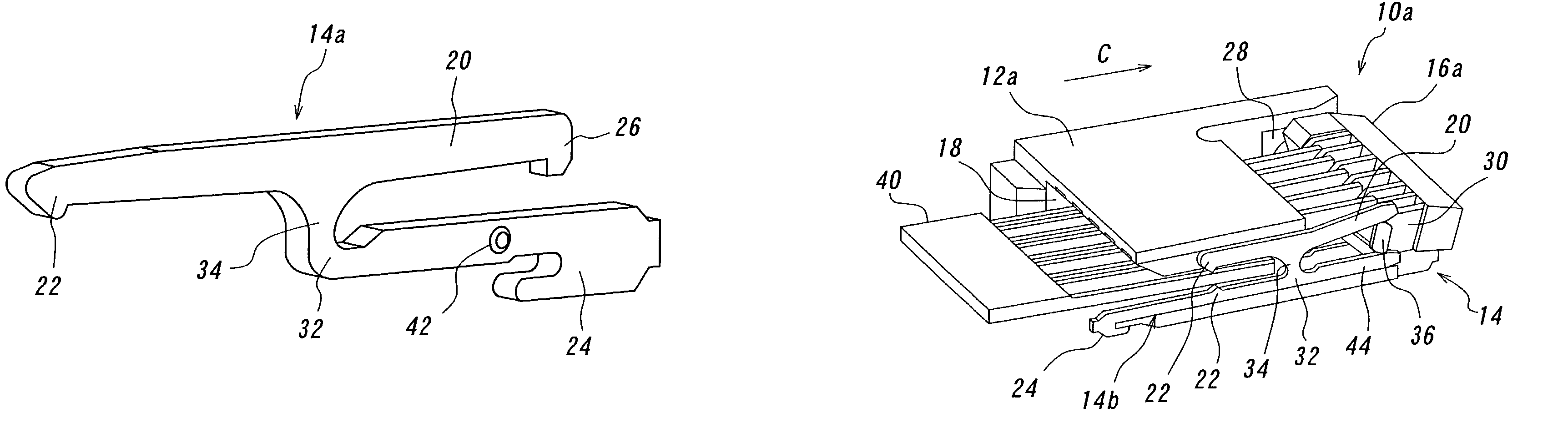
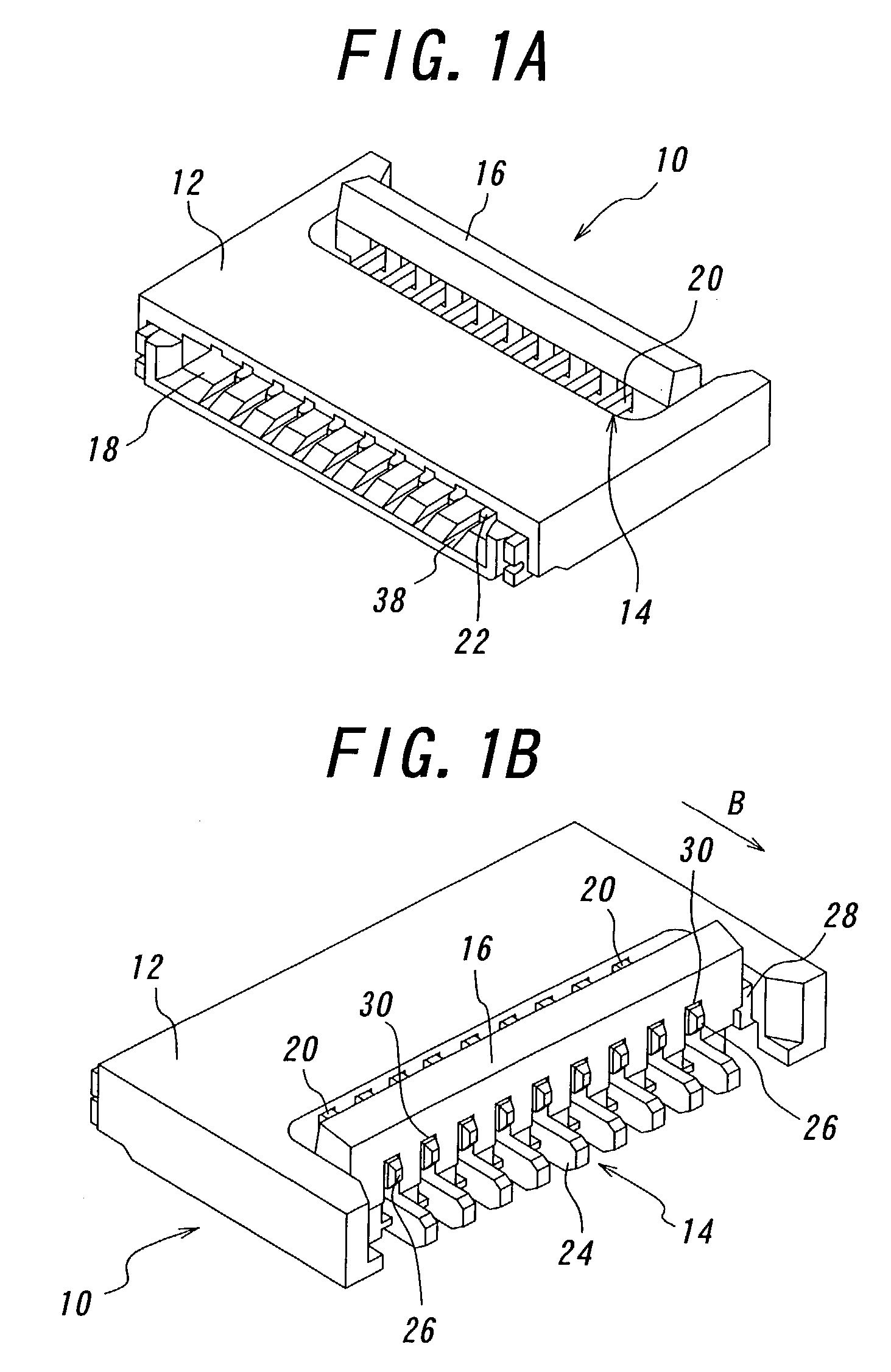
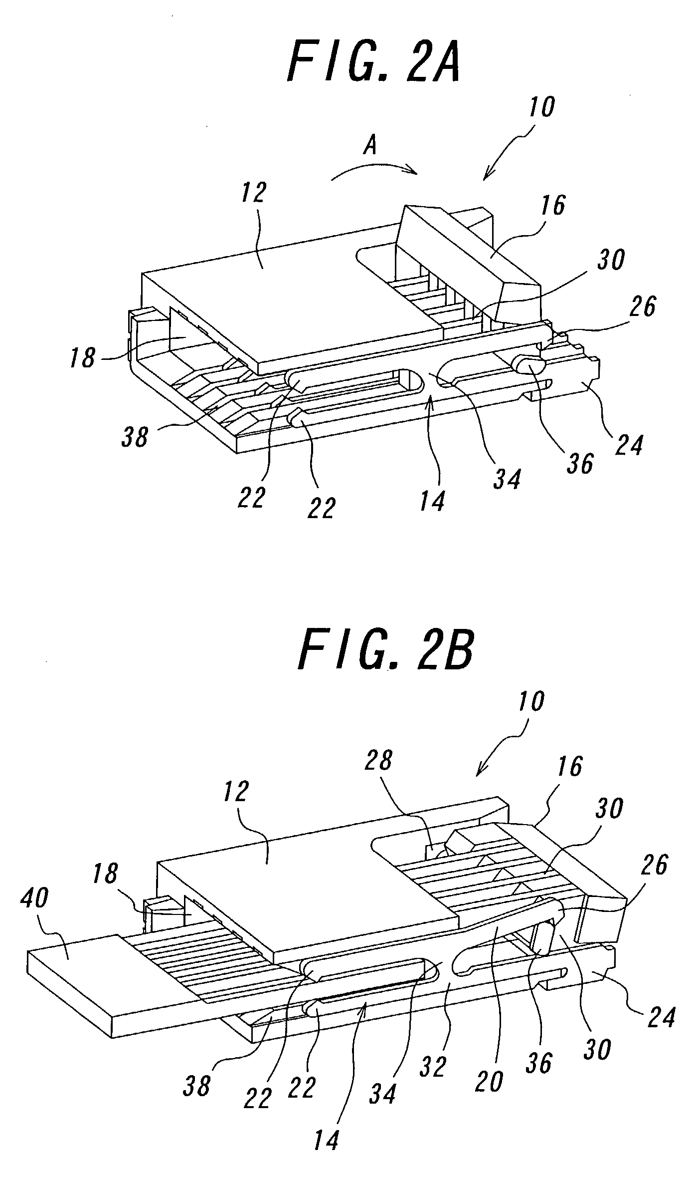
[0163]The connectors for achieving the first to sixth objects of the invention have novel features for bringing a flexible printed circuit board or flat cable into contact with electrical contacts, being divided into three constructions. The connector of the first construction mainly comprises a housing, contacts and a slider which is pivotally moved to urge the circuit board against the contacts. This type of connector is so-called “piano touch” type. The position where the slider is pivotally moved may be on the side of an insertion opening for the circuit board or on the side of connections of the contacts.

[0164]The connector of the second construction also mainly comprises a housing, contacts and a slider which is inserted into an insertion opening of the housing to urge the circuit board against the contacts. This type of connector is so-called “zero-insertion force” type. In other words, after the circuit board has been inserted through the insertion opening into the housing, ...


PUM


Abstract

A connector includes contacts each having a contact portion, an elastic portion and a fulcrum portion between the contact portion and a connection portion, and a pressure receiving portion; a housing fixing the contacts; and a slider having urging portions pivotally moved between the connection and pressure receiving portions of the contacts to urging the contact portions against the circuit board, thereby achieving reliable connection and miniaturization of the connector. In an aspect, the housing is formed on the side of a board insertion opening with a recessed portion for conducting the board. In another aspect, the contact includes upper and lower contact portions one above the other arranged alternately staggered so as to be connected to a circuit board having contact portions alternately staggered, so that no defective connection occurs, even if the circuit board is inserted erroneously upside down. In a further aspect, the connector further includes locking members having an engaging portion which engages an anchoring portion of the circuit board to prevent the circuit board from being removed. In one aspect, contacts of two kinds are inserted into the housing from opposite sides, respectively so that these contacts of the two kinds are into contact with the contact portions on respective surfaces of the circuit board. In a further aspect, moreover, a plate-shaped piece is provided in opposition to the contact portions of the contacts to prevent the housing from being deformed.

Description

BACKGROUND OF THE INVENTION[0001]The present invention relates to a connector for use in a mobile phone or cellular phone, notebook personal computer, digital camera or the like, and more particularly to a connector capable of reliably urging contacts against a flexible printed circuit board or flexible flat cable, facilitating conducting the circuit board or flat cable into the connector and at the same time achieving miniaturization of the connector, eliminating any defective connection even if the circuit board is inserted into the connector erroneously upside down, reliably locking the board or cable to the connector, miniaturizing the connector even in the case of the circuit board having contacts on both surfaces, and reinforcing the connector preparatory to mounting it onto the board or cable.[0002]In general, connectors for use in mobile phones, charge coupled device (CCD) cameras and the like are much thinner (so-called lighter and more compact connectors) and include conta...

Claims


Application Information

Patent Timeline
IPC IPC(8): H01R12/24H01R12/78H01R13/629H01R13/631
CPCH01R12/592H01R12/774H01R12/88H01R12/79H01R12/57H01R2201/16H01R2201/04
Inventor SUZUKI, MASAYUKIWATANABE, JUN-ICHI
Owner DDK LTD
Why Eureka
Try Eureka