
Color filter and manufacturing method thereof

a technology of color filter and manufacturing method, which is applied in the direction of photomechanical treatment originals, photo-taking processes, instruments, etc., can solve the problems of affecting the quality and efficiency of lcd, affecting the characteristics of subsequent, and affecting the quality of subsequent, so as to improve the quality of color filter and improve the efficiency of lcd assembly

Inactive Publication Date: 2006-05-16
HIMAX TECH LTD
View PDF2 Cites 4 Cited by
  • Summary
  • Abstract
  • Description
  • Claims
  • Application Information

AI Technical Summary

Benefits of technology

The invention provides a color filter and a manufacturing method that uses optical proximity correction (OPC) to create filtering units that are flat and tightly coupled without any dimples at the corners. This improves the quality of the color filter and the efficiency of LCD assembly. The color filter has a number of first filtering units, second filtering units, and third filtering units, which are manufactured using different mask patterns. The first compensating portions enable smooth coupling of the first filtering units with the adjacent second filtering units. The manufacturing method involves using the first mask to pattern a photo-resist to form the first filtering units and using the second mask to pattern a photo-resist to form the second filtering units. The technical effects of the invention are improved quality of color filter and efficiency of LCD assembly.

Problems solved by technology

The unevenness affects the characteristics of subsequent liquid crystal package.
The dimples would cause abnormal liquid crystal arrangement in subsequent liquid crystal package, leading to “light leakage” during the operation of the LCD and largely affecting the quality and the efficiency of the LCD.

Method used


Image

  • Color filter and manufacturing method thereof
  • Color filter and manufacturing method thereof
  • Color filter and manufacturing method thereof

Examples


Embodiment Construction

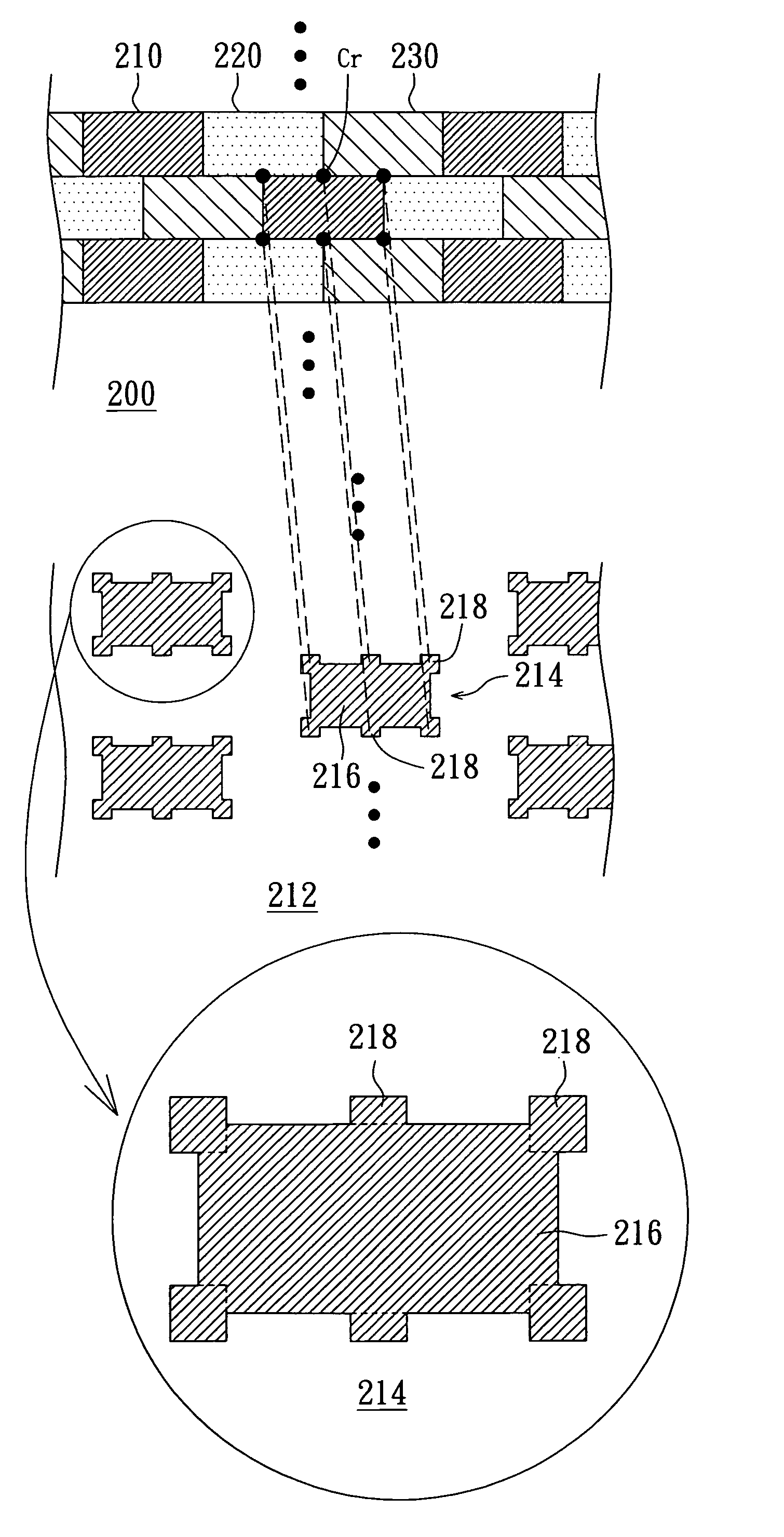
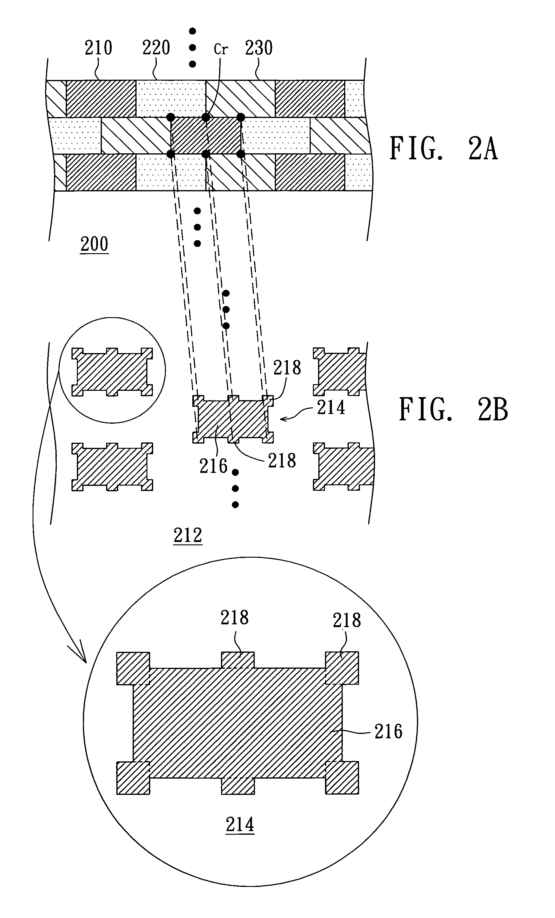
[0023]The feature of the color filter of the invention lies in applying optical proximity correction (OPC) technology to the manufacturing process of the color filter in the invention. The OPC is performed on the mask pattern of the filter to compensate the corner part of each filter, so that the adjacent corners of the filters can have a smooth coupling, not only improving the quality of the color filter but also increasing the efficiency in subsequent LCD assembly.

[0024]Referring to FIG. 2A, a top view of a color filter according to a preferred embodiment of the invention is shown. The color filter 200, which can be a delta-type color filter, comprises a number of red filtering units 210, a number of green filtering units 220 and a number of blue filtering units 230. In actual manufacturing process, the red filtering units 210 are manufactured according to a number of first patterns 214 of a first mask 212, wherein the first patterns 214 comprise a first main pattern portion 216 a...


PUM

PropertyMeasurementUnit
flatnessaaaaaaaaaa
flatnessaaaaaaaaaa
weightaaaaaaaaaa

Abstract

A color filter comprising first filtering units, second filtering units, and third filtering units is provided. The first filtering unit is manufactured according to a number of first pattern of a first mask, wherein each of the first patterns comprises a first main pattern portion and a number of first compensating portions. The second filtering unit is manufactured according to a number of second patterns of the second mask. The first compensating portions enable each first filtering unit to be smoothly coupled with the adjacent second filtering unit.

Description

[0001]This application claims the benefit of Taiwan application Ser. No. 93118186, filed Jun. 23, 2004, the subject matter of which is incorporated herein by reference.BACKGROUND OF THE INVENTION[0002]1. Field of the Invention[0003]The invention relates in general to a color filter and manufacturing method thereof, and more particularly to a color filter using optical proximity correction (OPC) technology and manufacturing method thereof.[0004]2. Description of the Related Art[0005]With the features of light weight, low power consumption and small volume, liquid crystal display (LCD) has gradually replaced CRT display and is now widely applied in electronic devices such as a notebook computer, personal digital assistant (PDA), mobile phone and liquid crystal TV. The design of color filter, an essential part to an LCD, greatly affects the quality and efficiency of the LCD.[0006]Referring to FIG. 1A, a top view of the structure of a conventional delta-type color filter is shown. The c...

Claims


Application Information

Patent Timeline
Patent Type & Authority Patents(United States)
IPC IPC(8): G02B5/20G02F1/1335A01K61/00G02B5/22G02B5/23
CPCG02B5/201G02F1/133514G02B5/223
Inventor CHEN, WEI-HSIAOHSIEH, MENG-HSUN
Owner HIMAX TECH LTD
Learn More