Positioning two elements using an alignment target with a designed offset

a technology of offset and alignment target, applied in the field of alignment control, can solve the problems of increasing difficulty in aligning one layer with the other, increasing the difficulty of alignment, and the use of coherent light, so as to achieve the effect of minimizing the alignment error

Inactive Publication Date: 2006-05-16
ONTO INNOVATION INC
View PDF43 Cites 70 Cited by
  • Summary
  • Abstract
  • Description
  • Claims
  • Application Information

AI Technical Summary

Benefits of technology

[0016]Another embodiment of the present invention is an apparatus for positioning a first element with a second element. The apparatus includes an alignment target having at least one periodic pattern on the first element and at least one periodic pattern on the second element, the alignment target including at least two locations, at least one of which has a designed in offset between the periodic patterns. If both locations have a designed in offset the offsets may be of the same magnitude in opposite directions. The apparatus includes a light source for producing light to be incident on the at least two locations of the alignment target and a light detector for detecting light after reacting with the two locations of the alignment target. The apparatus further includes a processor with a computer-usable medium having computer-readable program code embodied therein for causing the processor to calculate the difference between the detected light from the two locations and using the difference to determine if the first element and the second element are aligned. The apparatus includes a stage that is controlled by the processor and that moves one of the elements with respect to the other element to minimize the alignment error.

Problems solved by technology

As the integrated circuit feature sizes continue to decrease to provide increasing circuit density, it becomes increasingly difficult to align one layer with another.
One disadvantage of alignment system 50 is that coherent light is used.
While multiple coherent light sources may be used to avoid this disadvantage, the use of multiple light sources adds complexity and cost.
Advantageously, the calculated difference is extremely sensitive to any alignment error.
A slight alignment error will produce a relatively large, and easily detected, calculated difference.

Method used


Image

  • Positioning two elements using an alignment target with a designed offset
  • Positioning two elements using an alignment target with a designed offset
  • Positioning two elements using an alignment target with a designed offset

Examples


Embodiment Construction

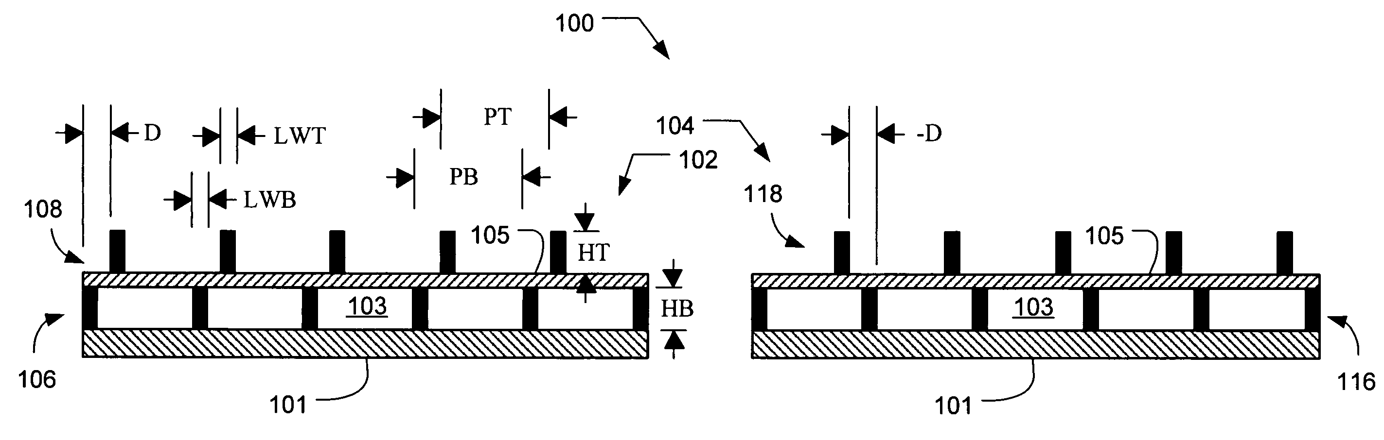
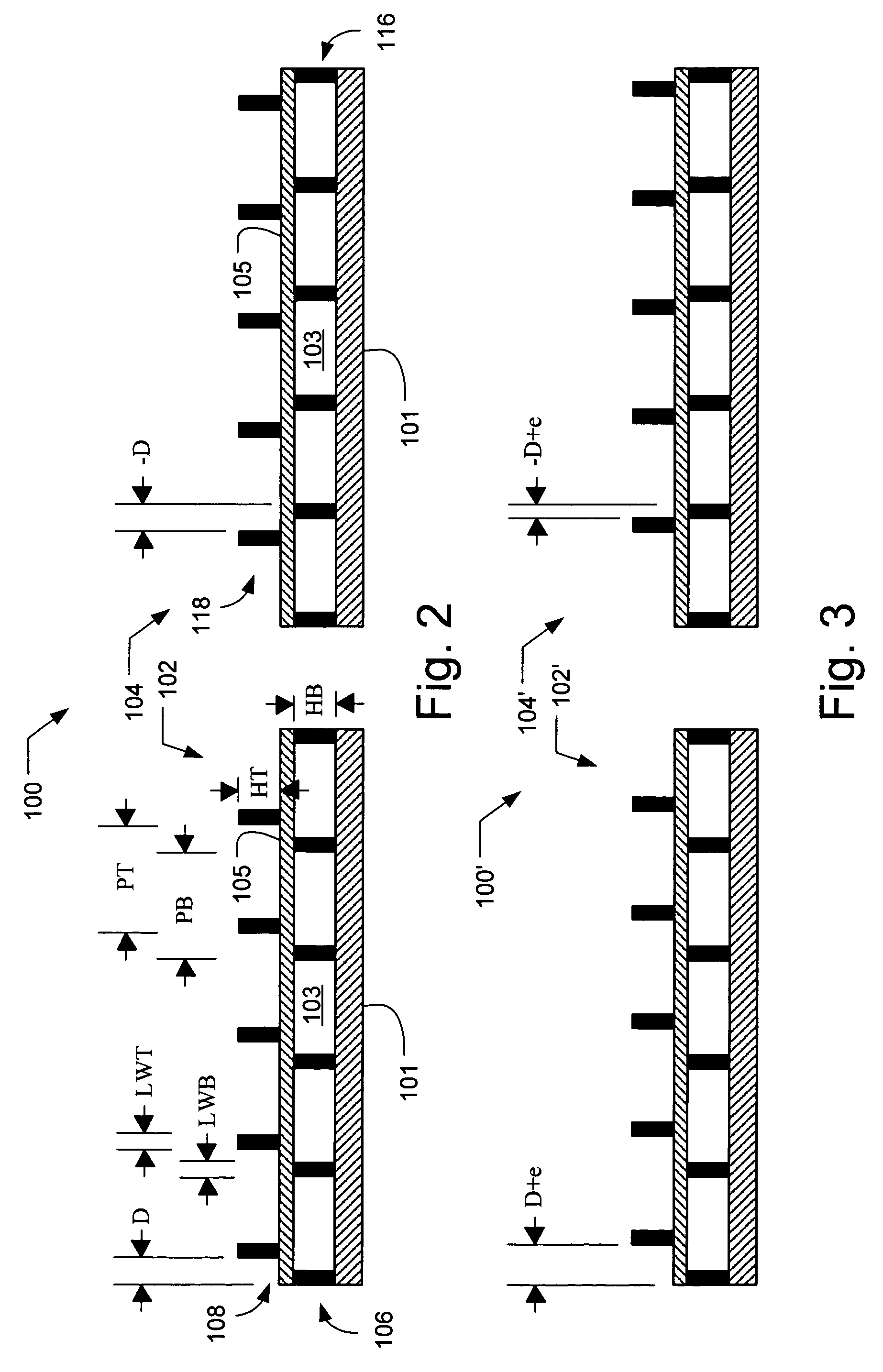
[0049]In accordance with an embodiment of the present invention, an alignment system aligns two elements using an alignment target that includes at least one periodic pattern on one element that is aligned relative to another periodic pattern on the other element. The alignment target includes at least two locations, i.e., areas of the alignment target, at least one of which has a designed in offset between the periodic patterns. For example, both locations can have a designed in offset that is equal in magnitude but opposite in direction. Alternatively, the magnitudes may differ and / or the directions may be non-parallel. The alignment target may be used to determine the alignment error between any two elements, e.g., between the lens and the substrate and / or reticle in an exposure tool, any two stages, or any other items to be aligned. Advantageously, the alignment target of the present invention is relatively insensitive to unintentional rotation of the top element with respect to...


PUM


Abstract

An alignment system for aligning two elements includes an alignment target with periodic patterns on each element. The alignment target includes two locations, at least one of which has a designed in offset. If desired, both locations may have designed in offsets of the same magnitude but in opposite directions. The diffraction patterns produced at the two locations are compared. If the difference between the patterns is at a minimum, the elements are properly aligned. When an alignment error is introduced, however, the calculated difference can be used to determine the error. In another embodiment, bands in the moiré fringes from the different locations may be compared to determine the alignment error. The two elements may then be moved relative to each other to minimize the alignment error. Thus, the alignment target may advantageously be used in any alignment system, such as an exposure tool.

Description

BACKGROUND OF THE INVENTION[0001]1. Field of the Invention[0002]The present invention relates to alignment control, and in particular to an alignment system that uses an alignment target that includes at two locations having designed in offsets.[0003]2. Discussion of the Related Art[0004]Semiconductor processing for forming integrated circuits requires a series of processing steps. These processing steps include the deposition and patterning of material layers such as insulating layers, polysilicon layers, and metal layers. The material layers are typically patterned using a photoresist layer that is patterned over the material layer using a photomask or reticle. As the integrated circuit feature sizes continue to decrease to provide increasing circuit density, it becomes increasingly difficult to align one layer with another.[0005]During processing, the substrate is moved from one location to the next so that different areas, e.g., dies, on the substrate can be exposed. The alignme...

Claims


Application Information

Patent Timeline
Patent Type & Authority Patents(United States)
IPC IPC(8): G01B11/00
CPCG03F7/70633G03F9/7084G03F9/7076
Inventor YANG, WEIDONGLOWE-WEBB, ROGER R.HEATON, JOHN D.
Owner ONTO INNOVATION INC
Why Eureka
Try Eureka