Switching power supply

Inactive Publication Date: 2006-05-16
PANASONIC CORP
View PDF8 Cites 29 Cited by
  • Summary
  • Abstract
  • Description
  • Claims
  • Application Information

AI Technical Summary

Benefits of technology

[0017]In order to solve the problems encountered in the above-mentioned conventional switching power supplies, the present invention is intended to make load sharing uniform by connecting the inpu

Problems solved by technology

In addition, in a switching power supply having this kind of configuration, when the amount of the output current increases, the losses in the windings of the transformer also increase.
This results in making the switching power supply lower in efficiency and larger in size.
As a result, in each of the DC-DC converters, the balance of the input voltages of the DC-DC converters is lost, and a load imbalance occurs in some cases.
If this kind of load imbalance becomes

Method used


Image

  • Switching power supply
  • Switching power supply
  • Switching power supply

Examples


embodiment 1

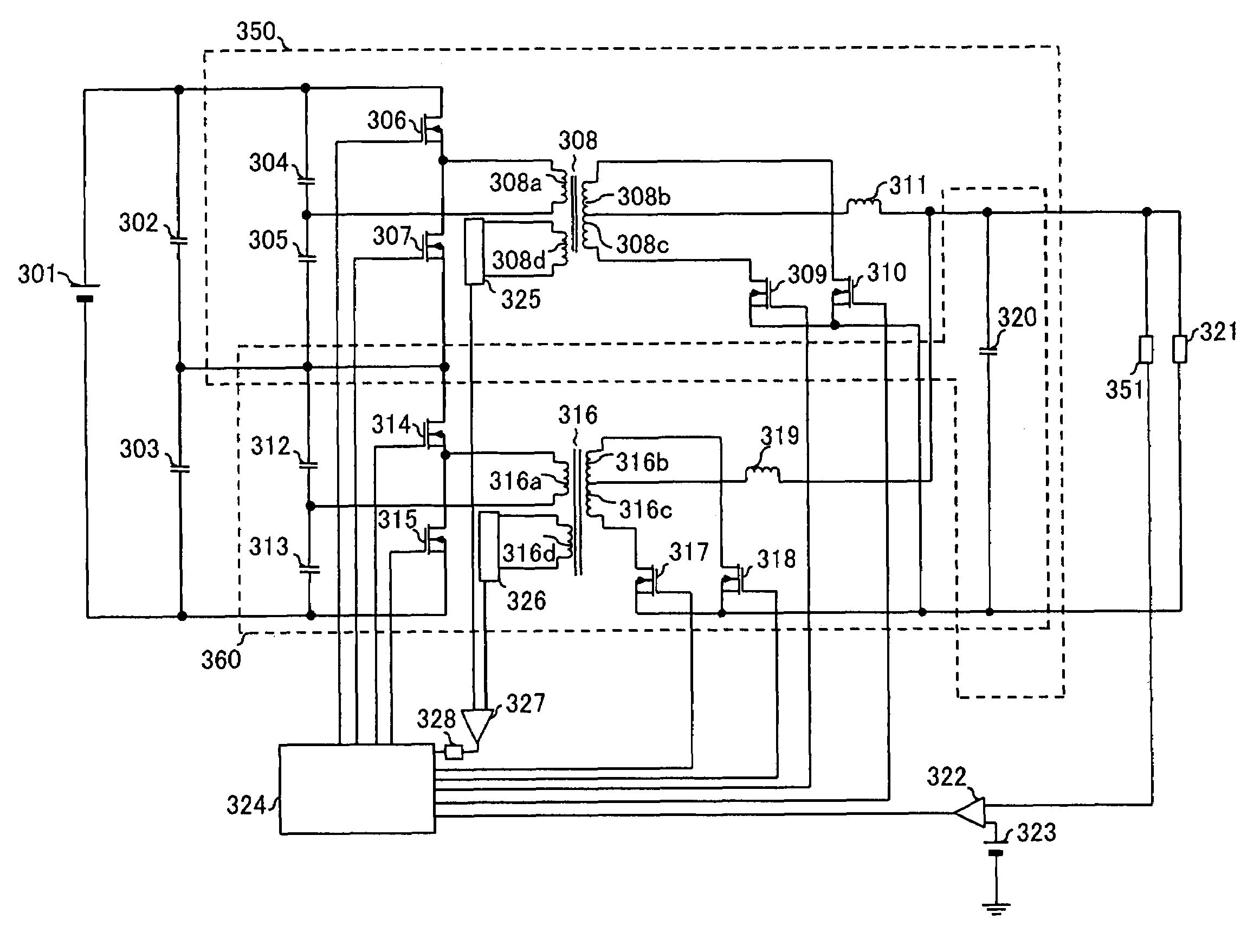
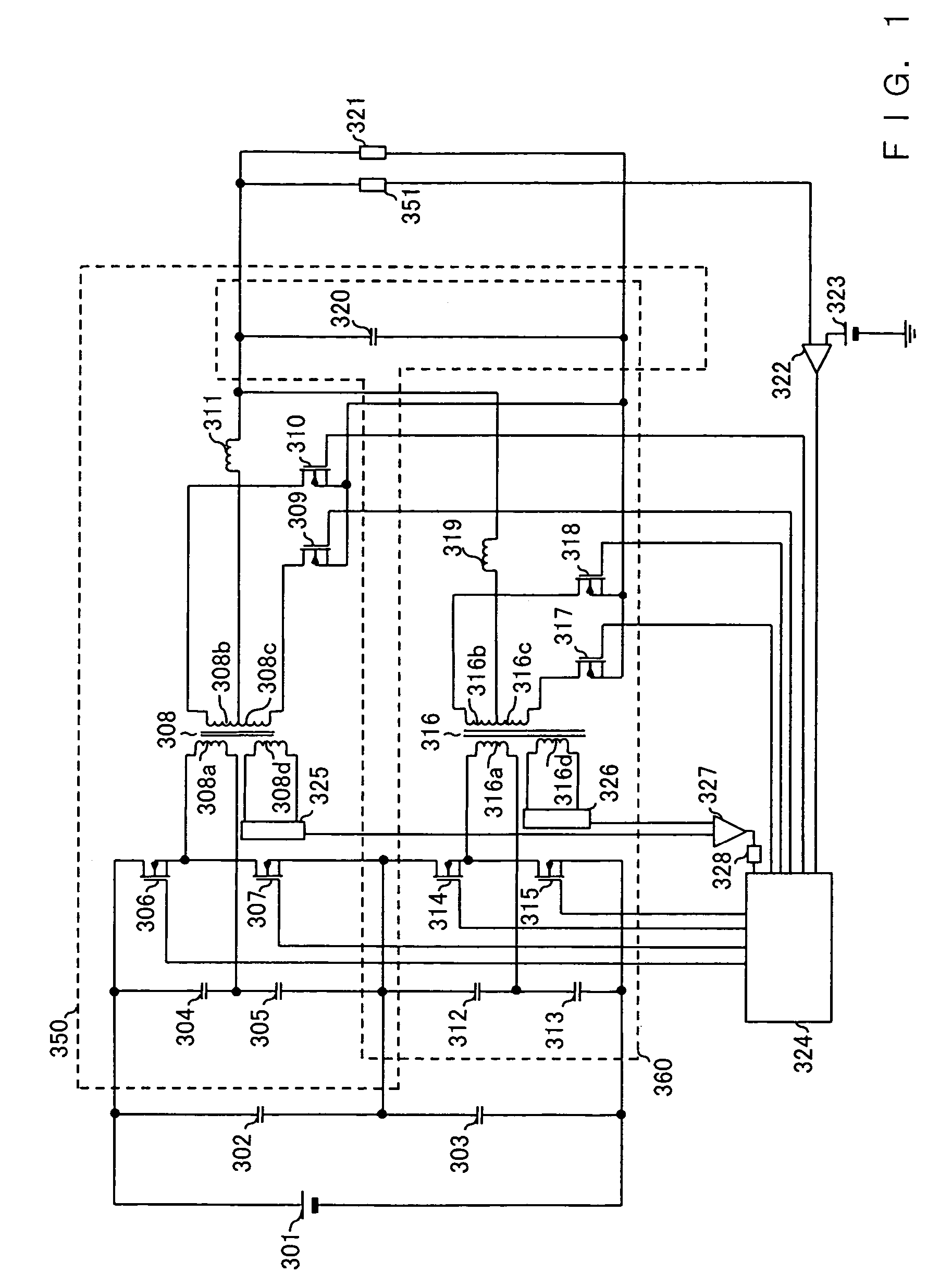
[0055]FIG. 1 is a circuit diagram showing the configuration of a switching power supply in accordance with Embodiment 1 of the present invention. In the switching power supply in accordance with Embodiment 1 shown in FIG. 1, the input sides of two half-bridge-type DC-DC converters (hereafter simply referred to as half-bridge converters) 350 and 360 are connected in series, and the output sides thereof are connected in parallel. In other words, in the switching power supply in accordance with Embodiment 1, two capacitors 302 and 303 are connected in series to divide the voltage of a DC power supply 301, and the divided voltages are applied to the first half-bridge converter 350 and the second half-bridge converter 360, respectively. In the case when the two DC-DC converters are a half-bridge type, the capacitors 302 and 303 can be omitted. This is because, in the circuit configuration of the half-bridge type, capacitors 304, 305, 312 and 313 are provided to carry out voltage division...

embodiment 2

[0092]Next, a switching power supply in accordance with Embodiment 2 of the present invention will be described. FIG. 4 is a circuit diagram showing the configuration of the switching power supply in accordance with Embodiment 2 of the present invention. In Embodiment 2, the components having the same functions, configurations and operations as those of the switching power supply in accordance with the above-mentioned Embodiment 1 are designated by the same names and numerals, and their explanations are omitted.

[0093]In the switching power supply in accordance with Embodiment 2, just as in the case of the above-mentioned Embodiment 1, the input sides of two half-bridge-type DC-DC converters (hereafter simply referred to as half-bridge converters) 450 and 451 are connected in series, and the output sides thereof are connected in parallel. In other words, in the switching power supply in accordance with Embodiment 2, two capacitors 302 and 303 are connected in series to divide the vol...

embodiment 3

[0111]Next, a switching power supply in accordance with Embodiment 3 of the present invention will be described. FIG. 6 is a circuit diagram showing the configuration of the switching power supply in accordance with Embodiment 3 of the present invention. In Embodiment 3, the components having the same functions, configurations and operations as those of the switching power supply in accordance with the above-mentioned Embodiment 1 are designated by the same names and numerals, and their explanations are omitted.

[0112]In the switching power supply in accordance with Embodiment 3, just as in the case of the above-mentioned Embodiment 1, the input sides of two half-bridge-type DC-DC converters (hereafter simply referred to as half-bridge converters) are connected in series, and the output sides thereof are connected in parallel. In other words, in the switching power supply in accordance with Embodiment 3, two capacitors 302 and 303 are connected in series to divide the voltage of a DC...


PUM


Abstract

A switching power supply wherein output voltage error detecting means detects the output voltage of DC-DC converters and generates an error signal, input voltage deviation detecting means detects voltages corresponding to the input voltages of the DC-DC converters to generate a deviation signal, and control means receives the error signal of the output voltage error detecting means and the deviation signal of the input voltage deviation detecting means and controls the driving of the DC-DC converters.

Description

BACKGROUND OF THE INVENTION[0001]The present invention relates to a switching power supply for supplying a stabilized DC voltage to industrial and consumer electronic appliances. More particularly, the present invention relates to improvements in the control stability of the DC-DC converter of a switching power supply.[0002]In recent years, as electronic appliances are made more inexpensive, compact, efficient and energy saving, switching power supplies having high output stability and being compact and efficient are demanded strongly. In particular, in the case of power supplies for supplying electric power to semiconductor devices, as semiconductor devices are made more highly integrated, power supplies having higher stability at a lower voltage and capable of supplying a larger current are demanded strongly.[0003]FIGS. 11A, 11B, 11C and 11D are circuit diagrams showing various configuration examples of DC-DC converters in conventional switching power supplies. FIG. 11A shows a fo...

Claims


Application Information

Patent Timeline
IPC IPC(8): H02M3/335H02M3/28
CPCH02M3/285H02M3/33592Y02B70/1475H02M2001/0074H02M2001/0022H02M1/0022H02M1/0074Y02B70/10
Inventor MATSUO, MITSUHIROYOSHIDA, KOJI
Owner PANASONIC CORP
Why Eureka
Try Eureka