X-ray scatter elimination by frequency shifting

a frequency shifting and scatter elimination technology, applied in tomography, instruments, television systems, etc., can solve the problems of physical impracticality in manufacture and maintenance of collimators, and the impracticality of conventional metal collimators such as those used in single-row ct imaging devices to block scatter radiation from the area detectors of cbct imaging devices, so as to improve the image quality of radiographic imaging devices, reduce scattering noise or eliminate the effect of nois

Inactive Publication Date: 2006-05-16
SIEMENS MEDICAL SOLUTIONS USA INC
View PDF1 Cites 37 Cited by
  • Summary
  • Abstract
  • Description
  • Claims
  • Application Information

AI Technical Summary

Benefits of technology

[0006]Accordingly, the present invention is directed to apparatus and methods for separating and filtering noise caused by X-ray scatter contaminations from the primary signal component of the signal reaching the detector assembly of a radiographic imaging device so that scatter induced noise may be reduced or eliminated from the signal allowing the image quality of the radiographic imaging device to be improved. In exemplary embodiments, the present invention employs a scatter removal screen or grating disposed between the object being imaged and the detector assembly. The grating has an absorption coefficient that varies periodically for varying the intensity of the X-ray radiation passed through the grating. This variation in intensity of the X-ray radiation causes the signal produced by the detector assembly to be amplitude modulated so that the frequency of the primary signal component of the signal is shifted from noise components of the signal caused by X-ray scatter contamination allowing the noise components of the signal to be filtered from the primary signal component. In this manner, scatter induced noise may be reduced or eliminated without the use of metal collimators or like shielding devices.

Problems solved by technology

Such collimators would be physically impractical to manufacture and maintain, especially in CBCT imaging devices employing megavolt (MV) sources, where the collimators would require substantial mass in order to block the high-energy photons created by the X-ray source.
As a result, conventional metal collimators such as those used in single-row CT imaging devices are impractical to be used to block scatter radiation from the area detectors for CBCT imaging devices.

Method used


Image

  • X-ray scatter elimination by frequency shifting
  • X-ray scatter elimination by frequency shifting
  • X-ray scatter elimination by frequency shifting

Examples


Embodiment Construction

[0020]Reference will now be made in detail to the presently preferred embodiments of the invention, examples of which are illustrated in the accompanying drawings.

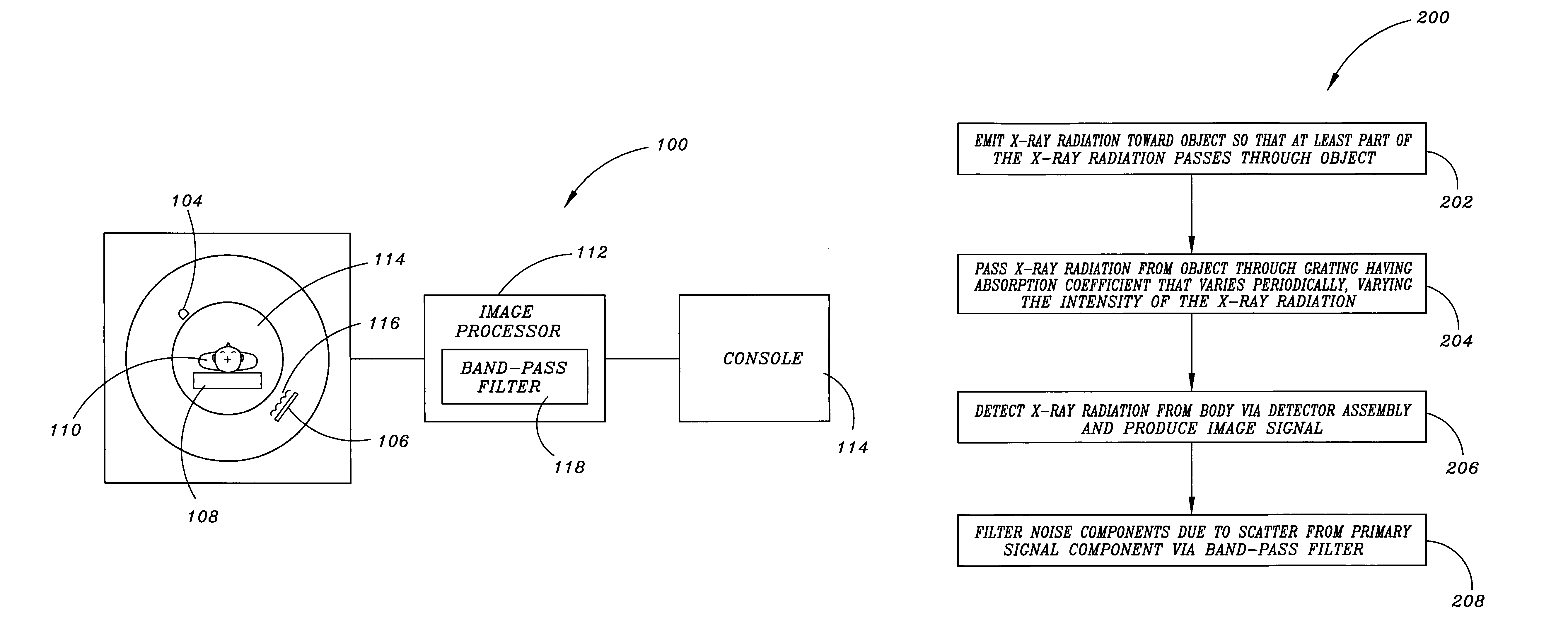
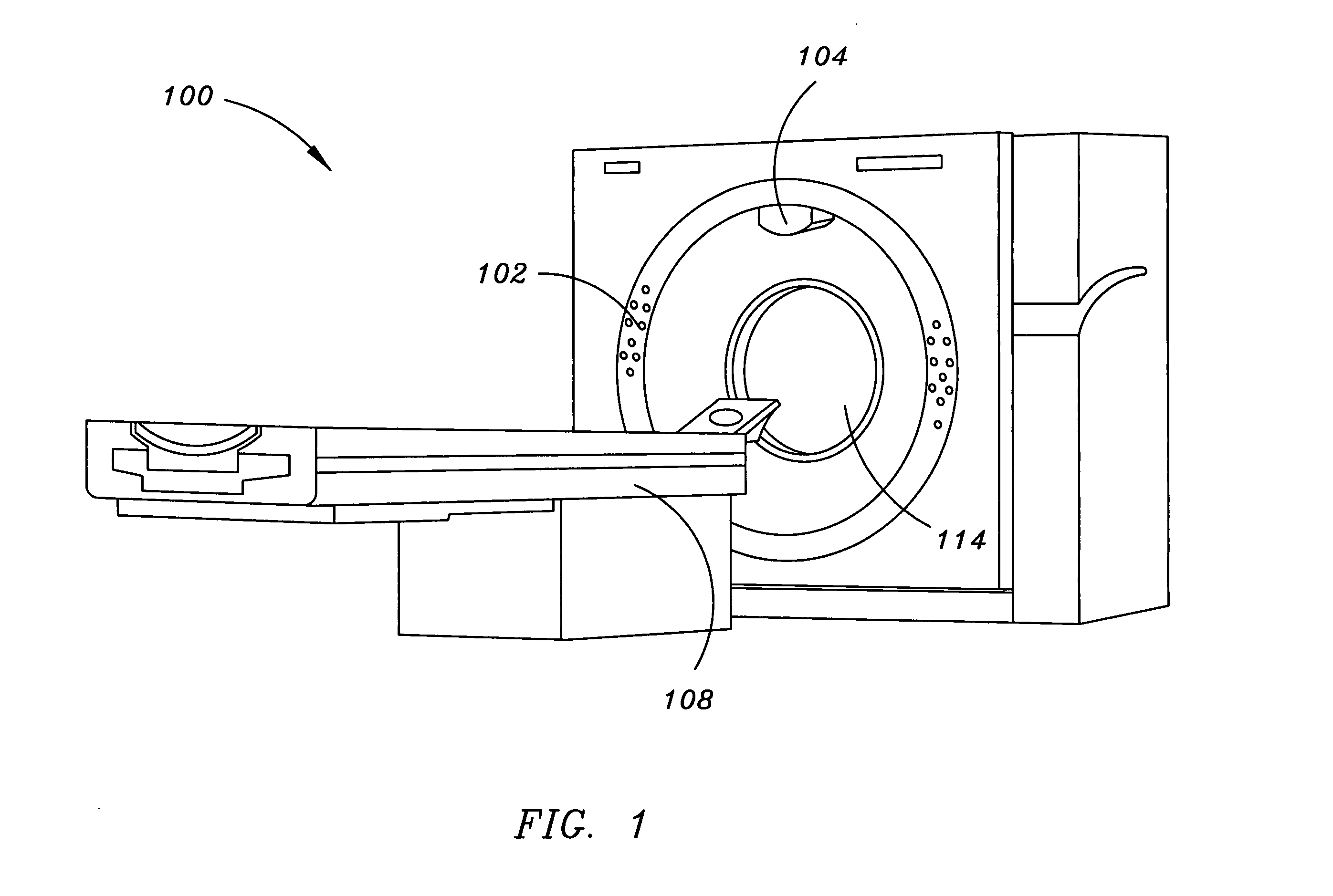
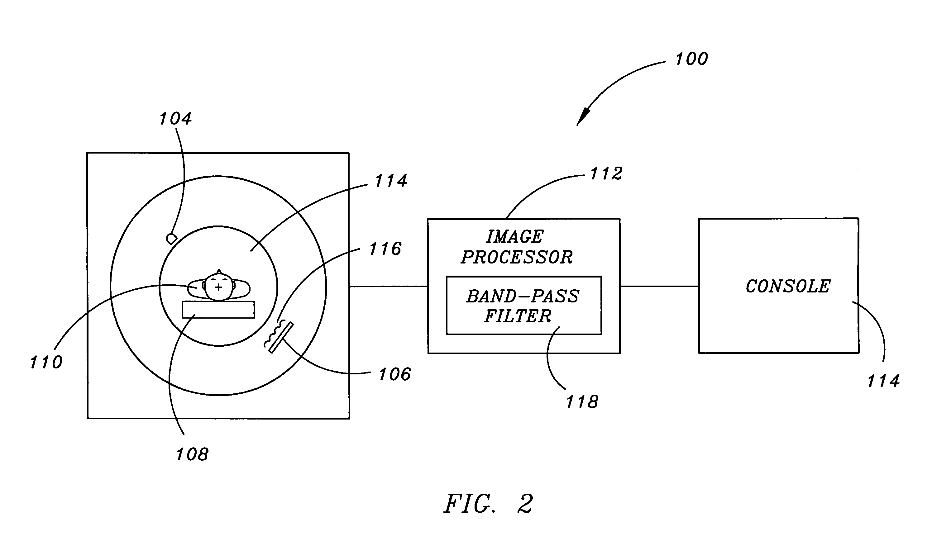
[0021]FIGS. 1 and 2 illustrate a radiographic imaging device 100 in accordance with an exemplary embodiment of the present invention. The radiographic imaging device 100 comprises a CBCT imaging device including a scanning unit or gantry 102 supporting an X-ray source 104 and a detector assembly 106, and a patient table 108 for supporting a patient 110 undergoing imaging. The X-ray source 104 emits X-ray radiation toward the body of a patient 110 lying on the patient table 108 so that at least part of the X-ray radiation passes through the body of the patient 110 to the detector assembly 106.

[0022]In exemplary embodiments, the radiographic imaging device 100 comprises a CBCT imaging device wherein the X-ray source 104 comprises a cone beam kV or MV source such as an X-ray tube, a linear accelerator assembly, or the like, w...


PUM

PropertyMeasurementUnit
widthaaaaaaaaaa
frequencyaaaaaaaaaa
spatial frequencyaaaaaaaaaa

Abstract

A method for separating and filtering noise caused by X-ray scatter contaminations from the primary signal component of the signal produced by the detector assembly of a radiographic imaging device employs a scatter removal screen or grating disposed between the object being imaged and the detector assembly. The grating has an absorption that varies periodically for varying the intensity of the X-ray radiation passed through the grating. This variation in intensity of the X-ray radiation causes the signal produced by the detector assembly to be amplitude modulated so that the frequency of the primary signal component is shifted from noise components of the signal caused by X-ray scatter contamination allowing the noise components to be filtered from the primary signal component so that scatter induced noise may be reduced or eliminated from the signal.

Description

BACKGROUND OF THE INVENTION[0001]The present invention relates generally to radiographic imaging devices, particularly, computed tomography (CT) imaging devices, and the like, and more specifically, to apparatus and methods for separating noise caused by X-ray scatter contaminations from the primary signal of the detector of a radiographic imaging device so that the scatter may be reduced or eliminated from the signal, thereby allowing the image quality of the radiographic imaging device to be improved.[0002]Single-row CT imaging devices or scanners, as well as CT imaging devices employing quasi-linear multi-row detectors, typically employ thin, straight metal collimators for eliminating scatter radiation. These metal collimators are oriented such that most of the scattered rays, which have their source at the scatter centers in the object being imaged (e.g., the body of a patient), intersect the collimator at oblique angles and are blocked. As a result, only rays approaching the de...

Claims


Application Information

Patent Timeline
Patent Type & Authority Patents(United States)
IPC IPC(8): G01N23/00
CPCA61B6/032A61B6/4291H04N5/32A61B6/5282
Inventor BANI-HASHEMI, ALIBLANZ, WOLF-EKKEHARDMALTZ, JONATHAN S.
Owner SIEMENS MEDICAL SOLUTIONS USA INC
Why Eureka
Try Eureka