
Integrated vehicle control system

a vehicle control system and integrated technology, applied in the field of integrated vehicle control systems, can solve the problems of inability to efficiently execute detailed abnormality detection capable of ranging widely and covering the entire apparatuses of the control system, and the automatic transmission may fail to smoothly execute the gear shift operation, so as to reduce the amount of communication data transmitted and efficiently execute abnormality detection

Active Publication Date: 2006-05-16
DENSO CORP
View PDF15 Cites 93 Cited by
  • Summary
  • Abstract
  • Description
  • Claims
  • Application Information

AI Technical Summary

Benefits of technology

The present invention provides an integrated vehicle control system that can efficiently execute abnormality detection and reduce the amount of communication data transmitted between electronic control apparatuses. The overall control apparatus determines operation directives for each individual control apparatus and performs abnormality detection processing to detect abnormalities in the entire system. The overall control apparatus also performs gateway processing to optimize data exchange among different networks. The invention allows for the development of a modular vehicle control system that can be easily adapted and modified, and also facilitates the standardization of communication data. The technical effects of the invention include improved fail-safe processing, efficient abnormality detection, and reduced data amount exchanged between electronic control apparatuses.

Problems solved by technology

However, according to the integrated vehicle control system using the above-described conventional network, it was difficult to efficiently execute abnormality detection ranging widely and covering the entire apparatuses of this control system.
In other words, it was impossible to execute detailed abnormality detection capable of ranging widely and covering the entire apparatuses of the control system and accurately identifying the root of each abnormality.
For example, the automatic transmission may fail to smoothly execute the gear shift operation.
The cause of this failure may reside in the automatic transmission itself, or may be originated from an engine when the engine has abnormality in its output torque.
Furthermore, due to abnormality of engine output, the cruise control or the traction control may not be performed appropriately.
Furthermore, according to the above-described conventional integrated vehicle control system, the data amount (i.e., communication data volume) transmitted or received via the communication line is so large that the recent requirements for multi-functions and high performance cannot be realized.

Method used


Image

  • Integrated vehicle control system
  • Integrated vehicle control system
  • Integrated vehicle control system

Examples


first embodiment

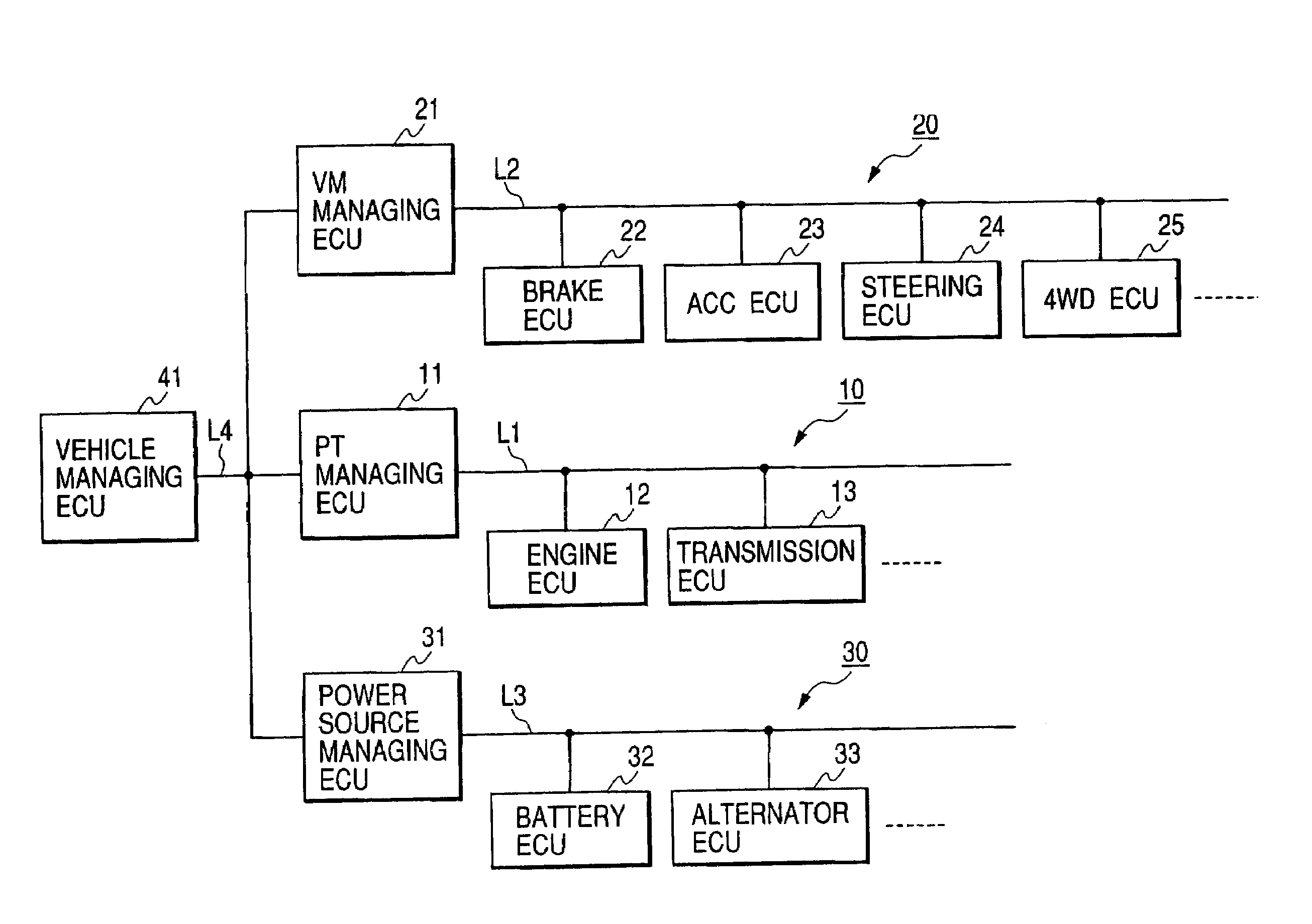
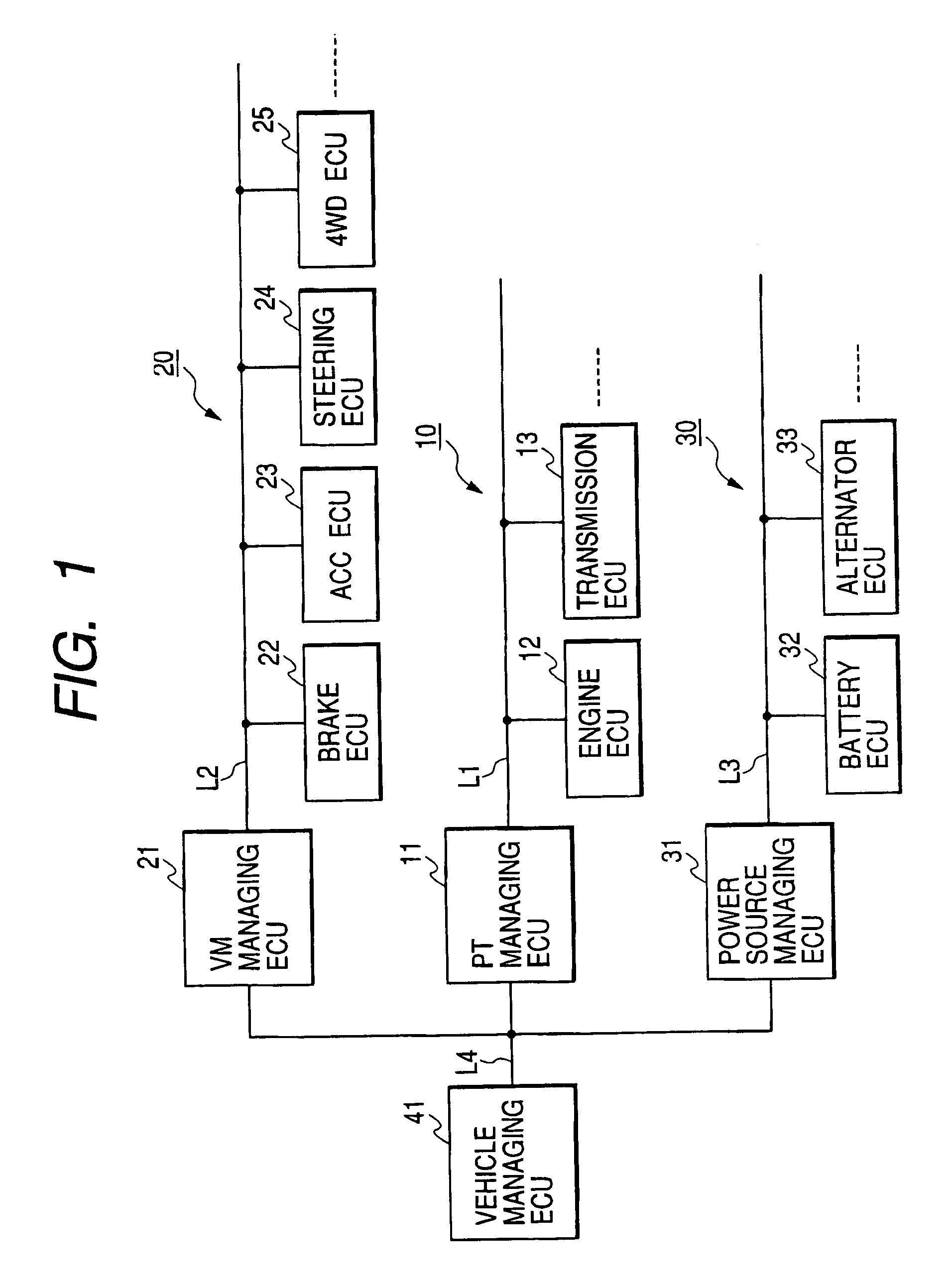
[0042]FIG. 1 is a block diagram showing the arrangement of an integrated vehicle control system in accordance with a first embodiment of this invention.

[0043]As shown in FIG. 1, the integrated vehicle control system of the first embodiment includes a power train network (i.e., a network for controlling power train devices) 10, a vehicle motion network (i.e., a network for controlling vehicle behaviors) 20, and a power source network (i.e., a network for controlling internal power sources equipped in an automotive vehicle) 30.

[0044]The power train network 10 includes an engine ECU 12 controlling an engine, a transmission ECU 13 controlling an automatic transmission, and a PT (i.e., Power Train) managing ECU 11 outputting operation directives to these ECUs 12 and 13 for collectively controlling the functions relating to driving force control of an automotive vehicle. The engine ECU 12, the transmission ECU 13, and the PT managing ECU 11 are mutually connected via a communication line ...

second embodiment

[0103]Next, an integrated vehicle control system in accordance with a second embodiment will be explained.

[0104]FIG. 5 is a block diagram showing the arrangement of the integrated vehicle control system in accordance with the second embodiment of this invention. In FIG. 5, the components identical with those disclosed in FIG. 1 are denoted by the same reference numerals and will not be explained again.

[0105]The integrated vehicle control system of the second embodiment is different from the integrated vehicle control system of the first embodiment in that the managing ECUs 11, 21, and 31 of respective networks and the vehicle managing ECU 41 shown in FIG. 1 are integrated into a single vehicle managing ECU 51.

[0106]Namely, according to the second embodiment, each of the communication lines L1, L2, and L3 of different functional networks is directly connected to only one vehicle managing ECU51. The vehicle managing ECU 51 performs the functions equivalent to those performed by the ma...


PUM


Abstract

An integrated vehicle control system includes various functionalized networks, such as power train group, vehicle motion group, and power source group, each including a plurality of ECUs connected via an individual communication line. A managing ECU in each network determines operation directives to be supplied to individual ECUs belonging to its own network based on information obtained from these individual ECUs as well as information obtained from other ECUs of different networks via a host communication line L4. The determined operation directives are transmitted to corresponding ECUs to cause respective individual ECUs to operate subordinately according to the given operation directives, thereby realizing a collective control of specific functions. The managing ECU also executes abnormality detection processing for detecting abnormality occurring in the integrated vehicle control system.

Description

BACKGROUND OF THE INVENTION[0001]This invention relates to an integrated vehicle control system which allows each electronic control apparatus to transmit and receive various data to and from other electronic control apparatuses for controlling various functions of a vehicle.[0002]In vehicles, especially in automotive vehicles, to satisfy recent market requirements including saving of fuel, improvement of safety, and improvement of convenience, many of the devices installed in an automotive vehicle are electronically controlled. To realize correlated operations and share mutual control information among electronic control apparatuses (hereinafter, referred to as ECU), respective ECUs are connected with each other via a common communication line so as to constitute a network (so-called LAN) to execute data communication.[0003]For example, FIG. 7 shows an example of this kind of conventional network including a control device network 100, an information device (AVC device) network 110...

Claims


Application Information

Patent Timeline
Patent Type & Authority Patents(United States)
IPC IPC(8): G06F7/00G06G7/70B60R16/02B60G17/0195B60K31/00B60R16/023B60W10/00B60W10/04B60W10/06B60W10/10B60W10/18B60W10/184B60W10/20B60W10/24B60W40/12B60W50/02B60W50/04F02D45/00G01M17/007G06F17/00H04L12/26
CPCB60G17/0195B60W50/04B60W50/02B60G2800/91B60G2800/92B60G2800/95B60G2800/96B60G2800/97B60W10/04B60W10/184B60W10/20B60W10/24B60G2800/98
Inventor AKIYAMA, SUSUMUTASHIRO, TSUTOMU
Owner DENSO CORP
Learn More