Tuck point tool

a tuck point and tool technology, applied in the field of masonry tools, can solve the problems of inconvenient handling and difficulty in handling, and achieve the effects of convenient storage in the pocket, convenient grasping and handling, and convenient manufactur

Inactive Publication Date: 2006-05-23
BENNETT HARRY
View PDF24 Cites 12 Cited by
  • Summary
  • Abstract
  • Description
  • Claims
  • Application Information

AI Technical Summary

Benefits of technology

[0010]Another object of the present invention is the provision of a masonry tuck tool that is inexpensive to manufacture and is conveniently small enough to store in a pocket while not in use yet is shaped such that it is easy to grasp and handle.

Problems solved by technology

This is inconvenient and difficult to handle.

Method used


Image

  • Tuck point tool
  • Tuck point tool

Examples


Embodiment Construction

[0016]Referring to the figures, like elements retain their indicators throughout the several views.

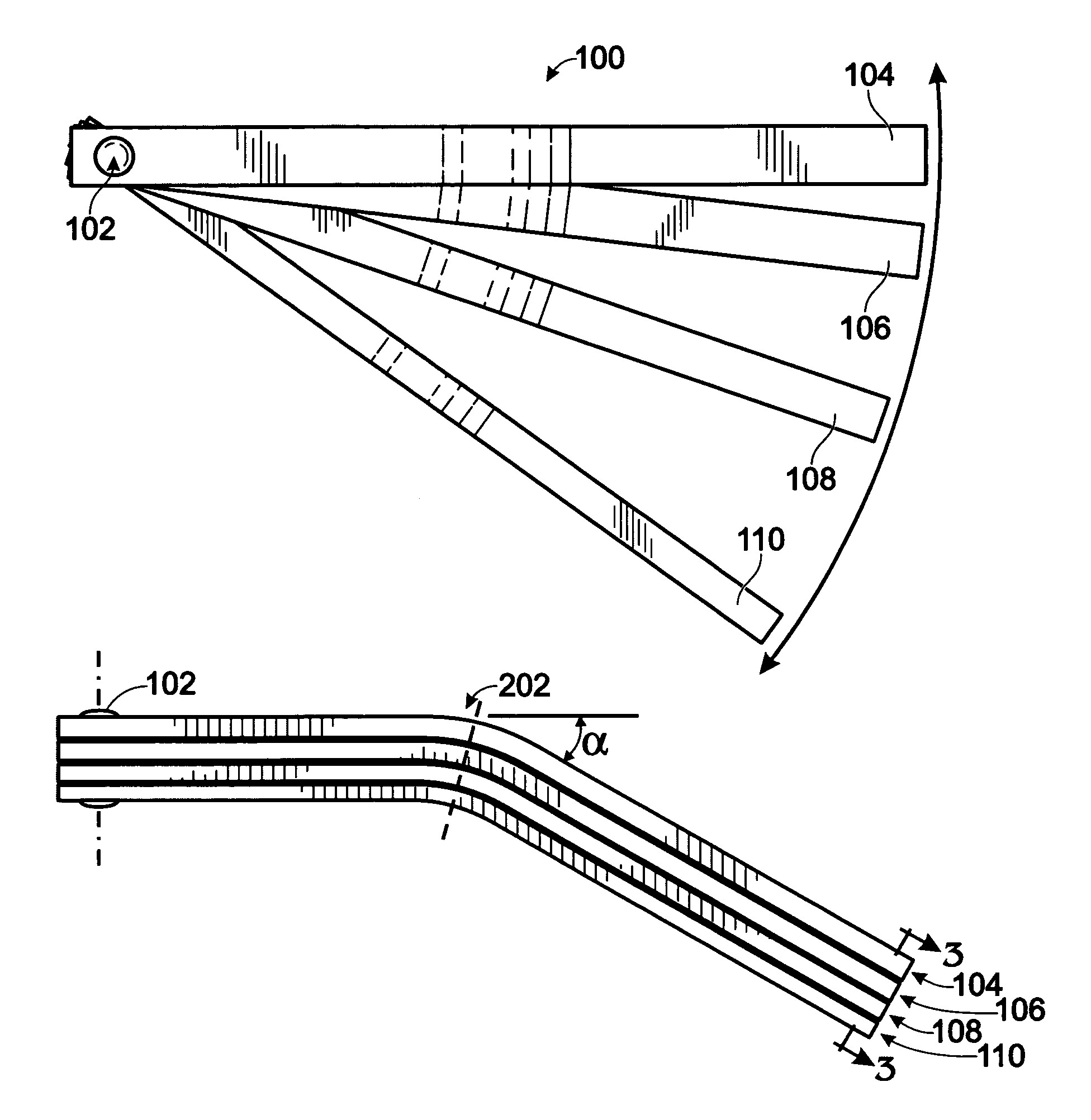
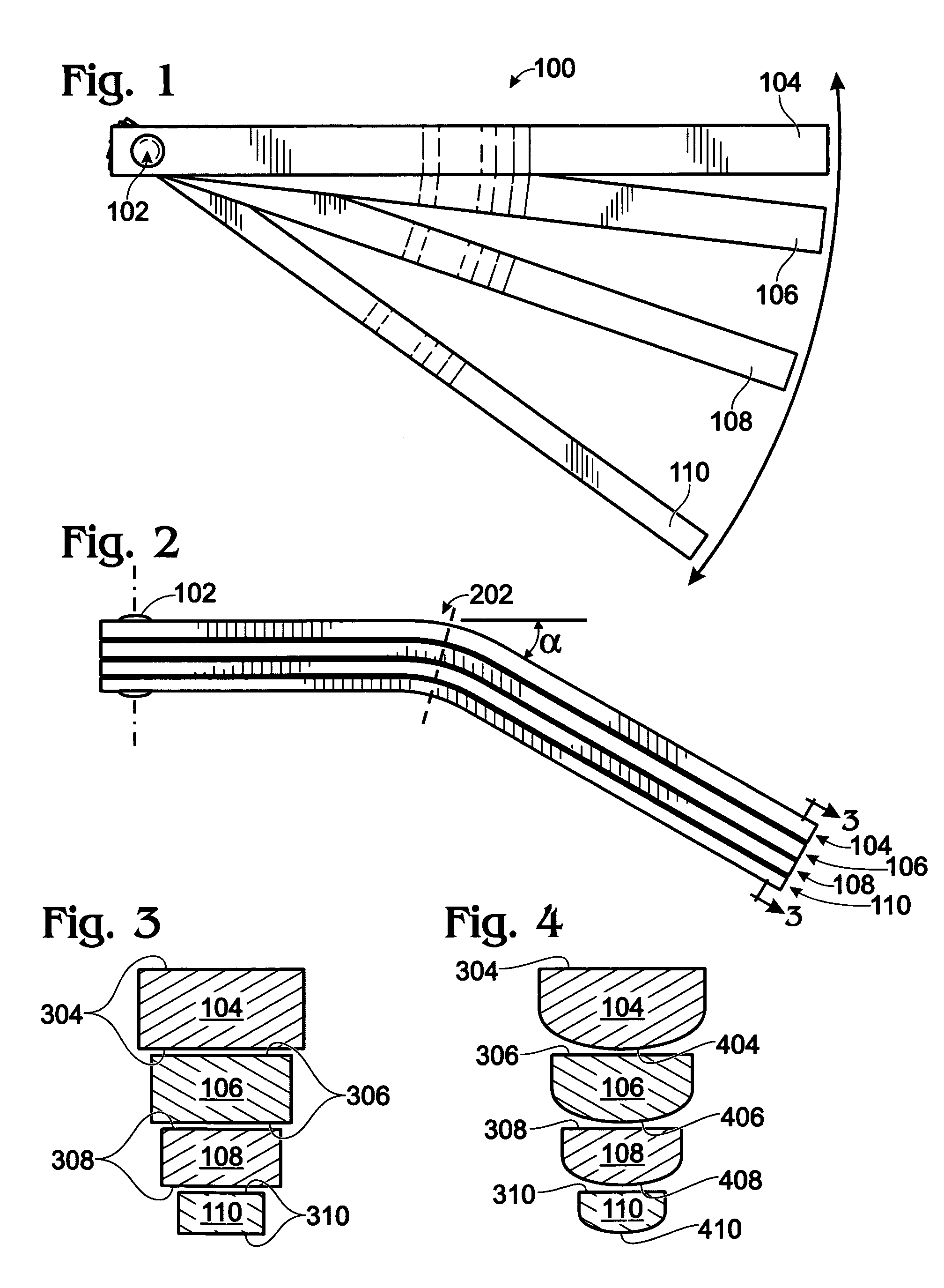
[0017]FIG. 1 is a plan view of the preferred embodiment of the present invention depicting Tuck Point Tool 100 in an open or “fanned out” state. The common widths for grout or mortar joints are ½″, ⅜″, ¼″, and ⅛″. As a result, in the preferred embodiment, Tuck Point Tool 100 has four individual tools—First Tuck Tool 104 representing the ½″ width, Second Tuck Tool 106 the ⅜″ width, Third Tuck Tool 108 the ¼″ width, and finally, Fourth Tuck Tool 110 the ⅛″. Each of the four tuck tools are pivotally attached to one another by Pivotal Component 102 disposed through one end of all of the tuck tools. When Tuck Point Tool 100 is not in use, all four tuck tools are slid together or stacked so they can be easily slipped into a jacket, shirt, or pants pocket similar to the stowing of a pen. When the mason wants to use one of the tuck tools, he simply rotates the needed tuck tool 180 degrees away...


PUM


Abstract

A masonry tuck point tool has a plurality of tuck blades pivotally attached at one end. Among the tuck blades is a selected tuck blade that has the desired width of the grout or mortar joint to be formed. There are also at lease one remaining tuck blade. All tuck blades have a distinct blade width and similar blade lengths. The selected tuck blade is pivoted approximately 180 degrees away from the remaining tuck blades thereby allowing the remaining tuck blades to be used as a handle at the one end while the opposite end of the selected tuck blade is used to strike a grout or mortar joint between two adjacent masonry elements.

Description

FIELD OF THE INVENTION[0001]The present invention relates to a masonry tool and more particularly to a masonry tuck point tool for tucking a joint between adjacent masonry elements.BACKGROUND OF THE INVENTION[0002]It is to be understood that the terminology “masonry elements” utilized throughout the specification is to be interpreted as including bricks, cinder blocks, compressed concrete slabs, decorative tile, or the like, and the joint therebetween may be formed of mortar, grout or other similar material.[0003]Additionally, “tucking a joint” is to be interpreted as meaning striking or finishing the joint between adjacent masonry elements.[0004]Tuck point tools are commonly used in masonry applications. One type of tuck tool is the generally S-shaped mortar striking tool wherein each end of the tool is rounded to a different radius to accommodate two different mortar widths. Another tool is a single size plastic grout finisher which is essentially a plastic thimble.[0005]Masonry o...

Claims


Application Information

Patent Timeline
Patent Type & Authority Patents(United States)
IPC IPC(8): E04G21/20E04F21/165
CPCE04F21/165E04F21/1652
Inventor BENNETT, HARRY
Owner BENNETT HARRY
Why Eureka
Try Eureka