Holding device

a technology of holding device and supporting device, which is applied in the direction of metal-working support, sheet joining, metal-working holders, etc., can solve the problems of not being usable, and neither of these devices address the problem

Inactive Publication Date: 2006-05-23
AUTO SERVICE TOOLS
View PDF15 Cites 25 Cited by
  • Summary
  • Abstract
  • Description
  • Claims
  • Application Information

AI Technical Summary

Benefits of technology

[0021]A screw threaded element may be provided for urging the clamping elemen...

Problems solved by technology

Service tools for holding camshafts and/or fuel injection pumps against rotation are known, but as supplied by motor manufacturers they are usually specifically designed for on...

Method used


Image

  • Holding device
  • Holding device
  • Holding device

Examples


first embodiment

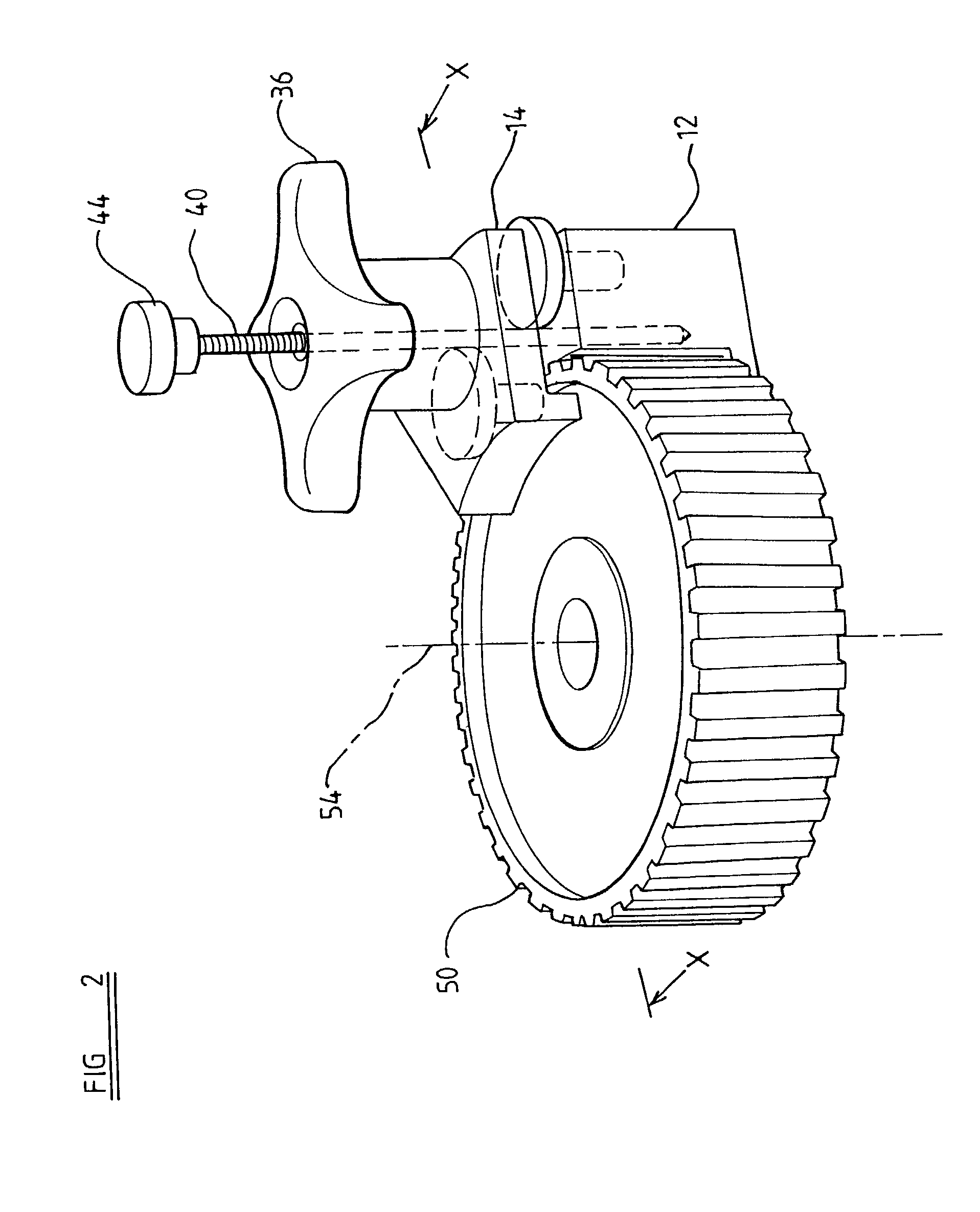
[0030]Referring firstly to FIGS. 2 and 3, there is shown holding device in accordance with the invention in use with a sprocket 50. The sprocket 50 is connected to a body in the form of an engine block 51 (not shown in FIG. 2) by a shaft 52 (also not shown in FIG. 2). The shaft 52 allows for rotation of the sprocket 50 about an axis 54. References to the radial and axial directions hereinafter, unless otherwise specified, are in relation to the axis 54.

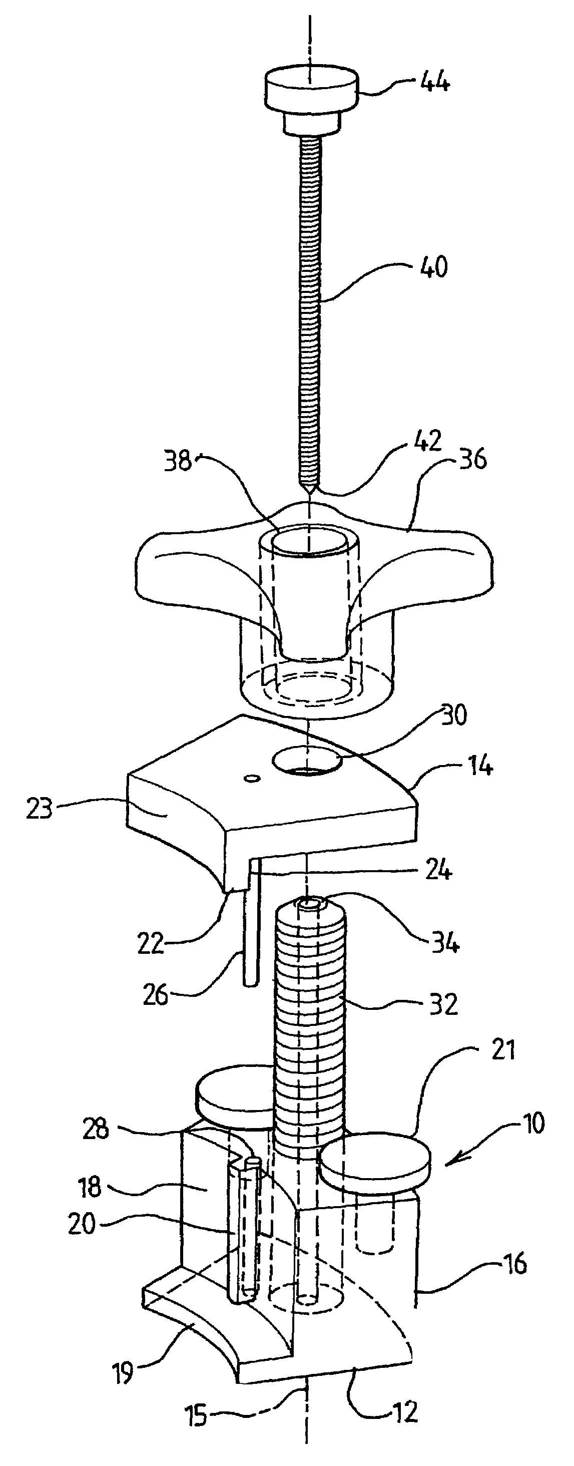
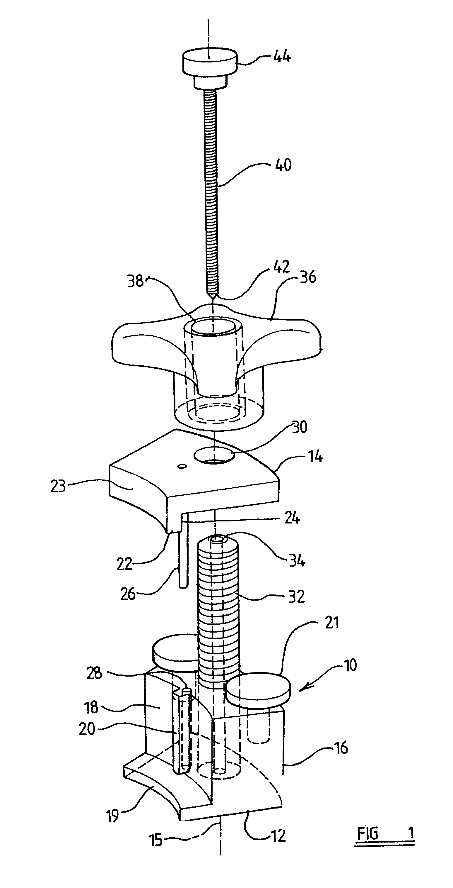
[0031]FIG. 1 shows an exploded perspective view of the first embodiment of holding device. It comprises a holding means, shown generally at 10. The holding means 10 comprises two clamping elements 12, 14, which are displaceable from one another along an axis 15, the axis 15 being substantially parallel, in use, to the axis 54. The clamping element 12 is part annular, having an external arcuate wall 16 and an internal arcuate wall 18. The internal arcuate wall 18 has, at its lower end, a radially inwardly extending lip 19, the lip 19 b...

second embodiment

[0034]Referring now to FIG. 4 there is shown a holding device in accordance with the present invention. Similar parts of the holding device shown in FIG. 2 have the same reference numerals as those of the holding device shown in FIG. 1, with the addition of 100.

[0035]The holding device shown in FIG. 4 is a compact version of the holding device shown in FIG. 2. Firstly, the locating pin26 and adjusting bolts 21 have been combined to provide an adjusting bolt 121 with a locating pin 126 extending upwardly from the flat head of the adjusting bolt 121. The locating pin 126 assists in maintaining alignment of the clamping elements 112, 114. The locating pin 126 engages in the bore 128 on the clamping element 114, when the clamping elements 112, 114 are aligned on top of each other. Secondly, the sides of both clamping elements 112, 114, parallel to the axis 115, taper towards one another as they extend away from the internal arcuate wall 118. Finally, the knurled knob 44 has been replace...


PUM


Abstract

A device for holding a rotary element stationary relative to a fixed body, the device comprising at least one element, adapted to engage with the rotary element to hold the device in a fixed position relative to the rotary element; and an engaging member, adapted to engage with the body to hold the device relative to the body.

Description

BACKGROUND TO THE INVENTION[0001]1. Field of the Invention[0002]The invention relates to a device for holding a rotary element stationary relative to a fixed body.[0003]The invention has been devised, particularly but not exclusively, for the purpose of holding a camshaft or a fuel injection pump of an internal combustion engine stationary relative to an engine casing. Commonly, a camshaft or fuel injection pump is driven in timed relation to the engine crankshaft by a toothed drive belt (timing belt) or chain entrained around toothed pulleys or sprockets (hereafter referred to as sprockets) on the crankshaft and the drive shaft of the camshaft or fuel injection pump. In order to prevent failure in service and possible engine damage, service schedules usually specify that the timing belt be replaced at predetermined time and / or mileage intervals. It is essential, when removing the timing belt for any reason, to ensure that the timing relationship between the camshaft or fuel injecti...

Claims


Application Information

Patent Timeline
IPC IPC(8): B25B27/14B23Q3/00B25B5/00B25B11/00B25B27/00F16B2/18F16B5/06
CPCF16H7/24Y10T403/7067Y10T29/53961Y10T29/53943Y10T29/53843
Inventor DAWSON, MALCOLM BRUCE
Owner AUTO SERVICE TOOLS
Why Eureka
Try Eureka