Turbocharged engine and method for preventing surging in compressor

a turbocharged engine and compressor technology, applied in the direction of machines/engines, electrical control, mechanical equipment, etc., can solve the problems of vibration damage, burst pressure sometimes remains, etc., and achieve the effect of reducing the intake pressure in the intake passage and preventing surging

Inactive Publication Date: 2006-05-23
ISUZU MOTORS LTD
View PDF14 Cites 28 Cited by
  • Summary
  • Abstract
  • Description
  • Claims
  • Application Information

AI Technical Summary

Benefits of technology

[0010]The present invention was created with the aforementioned problems in view and it is an object of the present invention to prevent surging in the compressor occurring when a vehicle is decelerating.
[0012]With this configuration, surging in the compressor occurring when the vehicle is decelerating can be prevented by reducing the intake pressure inside the intake passage when the vehicle is decelerating.
[0019]In accordance with the second aspect of the present invention, there is provided a method for preventing surging in a compressor of a turbocharged engine comprising an EGR unit having an EGR passage linking an intake passage and an exhaust passage and an EGR valve provided in the EGR passage, wherein the intake pressure in the intake passage is reduced by opening the EGR valve and causing part of the intake air present in the intake passage to flow into the exhaust passage via the EGR passage when a decision is made that the vehicle is decelerating.

Problems solved by technology

However, in a turbocharged engine, when a vehicle is decelerating, a burst pressure sometimes remains inside the intake passage and the intake pressure sometimes crosses the surge line of the turbocharger compressor.
If the surge line is crossed, surging is induced in the compressor, creating a risk of damage caused by vibrations or heat.

Method used


Image

  • Turbocharged engine and method for preventing surging in compressor
  • Turbocharged engine and method for preventing surging in compressor
  • Turbocharged engine and method for preventing surging in compressor

Examples


Embodiment Construction

[0023]The preferred embodiments of the present invention will be described below with reference to the appended drawings.

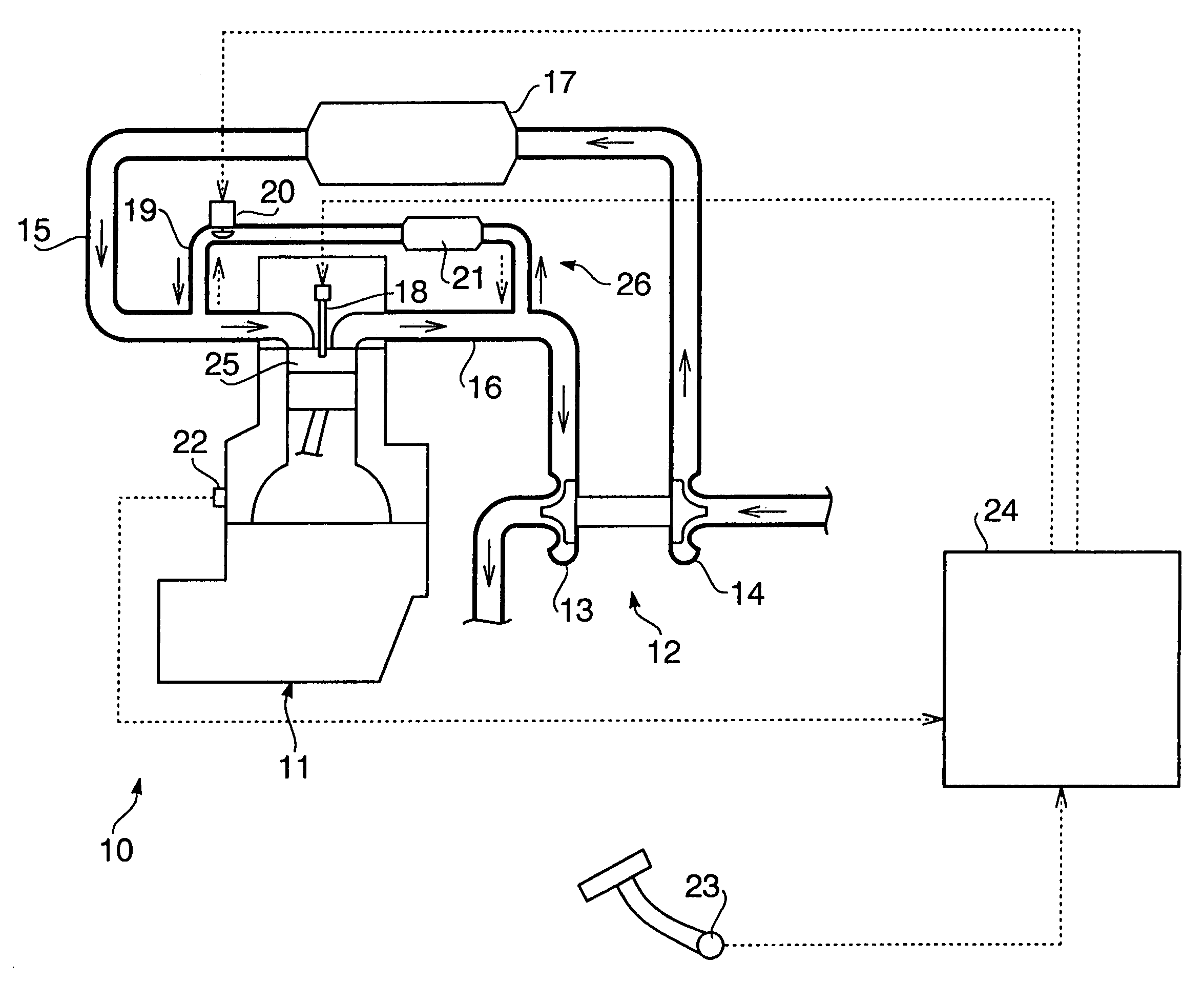
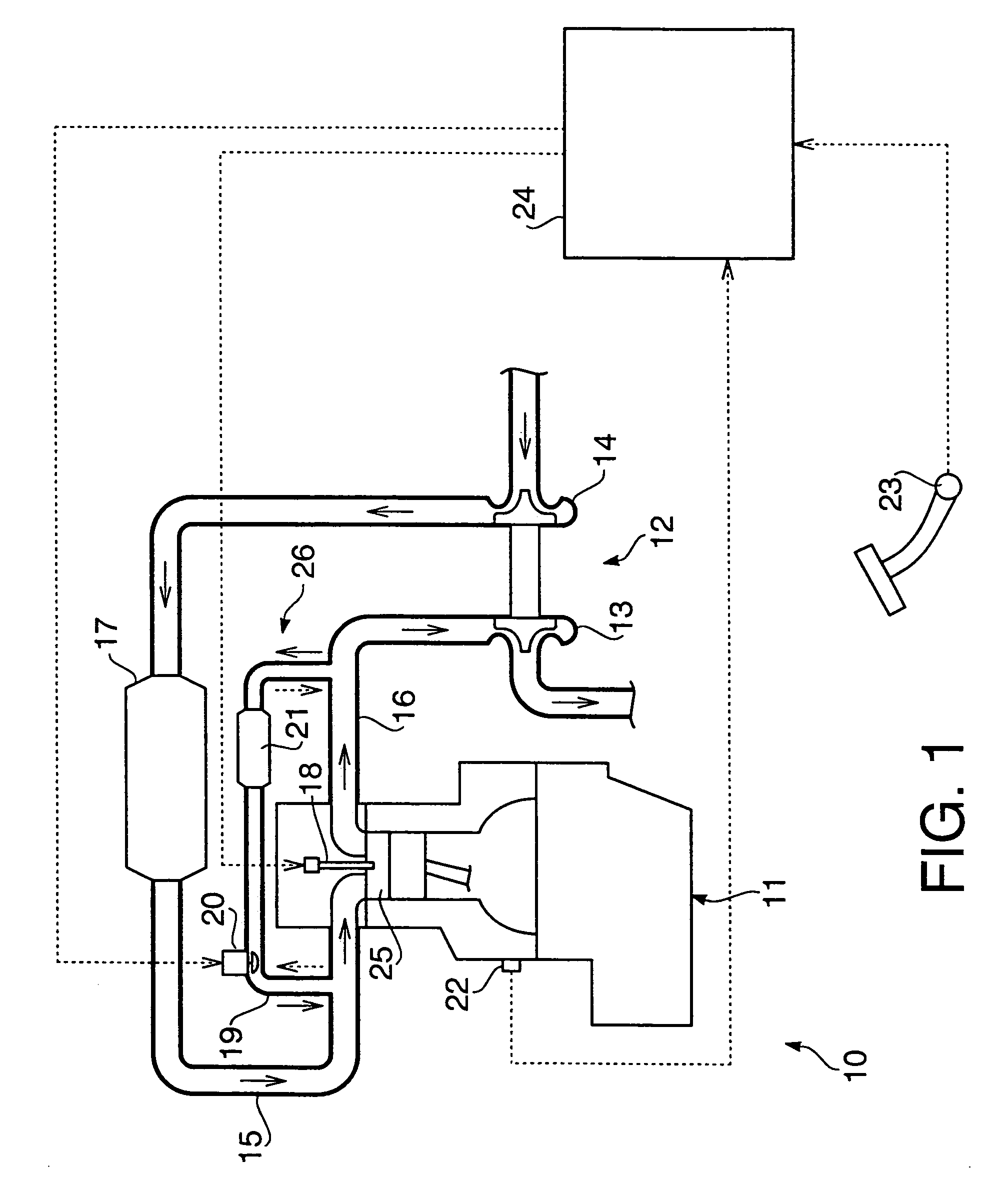
[0024]A turbocharged diesel engine of the present embodiment is shown in FIG. 1. A turbocharged diesel engine 10 comprises an engine body 11, a turbocharger 12, an intake passage 15, an exhaust passage 16, and an EGR unit 26.

[0025]The engine body 11 comprises a combustion chamber 25. Further, the engine body 11 also comprises a fuel injector 18 for injecting fuel into the combustion chamber 25 and an engine revolution speed sensor 22 serving as engine revolution speed detection means for detecting the engine revolution speed. The turbocharger 12 comprises a turbine 13 and a compressor 14, and the turbine 13 and compressor 14 are linked together by a rotary shaft.

[0026]The intake passage 15 is connected at the upstream side thereof to the compressor 14 and at the downstream side thereof to the combustion chamber 25. Furthermore, the intake passage 15 comprises an i...


PUM


Abstract

The turbocharged engine in accordance with the present invention comprises an EGR unit having an EGR passage linking an intake passage and an exhaust passage and an EGR valve provided in the EGR passage. The engine further comprises deceleration deciding unit for deciding as to whether a vehicle decelerates, and intake air release unit for opening the EGR valve and causing part of the intake air present in the intake passage to flow into the exhaust passage through the EGR passage when the deceleration deciding unit decides that the vehicle is decelerating.

Description

CROSS REFERENCE TO RELATED APPLICATION[0001]Applicants hereby claim foreign priority benefits under U.S.C. § 119 of Japanese Patent Application No. 2003-158299, filed on Jun. 3, 2003, and the content of which is herein incorporated by reference.BACKGROUND OF THE INVENTION[0002]1. Field of the Invention[0003]The present invention relates to a turbocharged engine comprising an EGR unit having an EGR passage linking an intake passage and an exhaust passage and an EGR valve provided in the EGR passage.[0004]2. Description of the Related Art[0005]An EGR unit (Exhaust Gas Recirculation unit) is generally known as a device for reducing the amount of NOx (nitrogen oxides) in exhaust gas. The EGR unit comprises an EGR passage linking an intake passage and an exhaust passage and an EGR valve provided in the EGR passage.[0006]The EGR unit opens the EGR valve, causes part of the exhaust gas present inside the exhaust passage to flow into the intake passage via the EGR passage, mixes this exhaus...

Claims


Application Information

Patent Timeline
Patent Type & Authority Patents(United States)
IPC IPC(8): F02B33/44F02B37/12F02M25/07F02B37/00F02B37/10F02B37/16F02B39/16F02D21/08F02D23/00F02D41/00
CPCF02B37/10F02B37/16F02D41/0005F02M25/0704F02D41/0055F02D41/0007Y02T10/47F02M25/0707Y02T10/144Y02T10/42F02M26/05F02M26/02Y02T10/12Y02T10/40
Inventor KONO, KAZUTOSHIHATANO, KENJIKAWAI, SHINICHIROOSADA, HIDEKI
Owner ISUZU MOTORS LTD
Why Eureka
Try Eureka